
-
Thank you for visiting HeavyEquipmentForums.com! Our objective is to provide industry professionals a place to gather to exchange questions, answers and ideas. We welcome you to register using the "Register" icon at the top of the page. We'd appreciate any help you can offer in spreading the word of our new site. The more members that join, the bigger resource for all to enjoy. Thank you!
You are using an out of date browser. It may not display this or other websites correctly.
You should upgrade or use an alternative browser.
You should upgrade or use an alternative browser.
Grapple Bucket pops off 2013 299D
- Thread starter Jeffrey Bandel
- Start date
digger doug
Senior Member
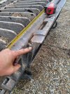
Follow the template/dimensions.I am going to cut this weld and the other weld on the other side, bend the whole bottom plate down to around 15 inches and reweld it. Sound like a plan?
Jeffrey Bandel
Senior Member
If I read the diagram correctly it is 15 7/8. Right about where I am shooting for.
digger doug
Senior Member
...and the correct angles.If I read the diagram correctly it is 15 7/8. Right about where I am shooting for.
Most likely need to cut the whole bottom piece off and move it. The correct angle is critical...and the correct angles.
Jeffrey Bandel
Senior Member
John V
Well-Known Member
Jeffrey Bandel
Senior Member
Great pic. Thanks. I'll check them in the morning.I measured this distance on my stump bucket and it was around 15 inches. My grapple is 16 inches. This pictures shows the bottom of the grapple bucket.
Tree Mulcher
Well-Known Member
I have had this problem before with wear on the top of the coupler plate on 299s being the issue. It is softer metal that wears. I have done weld buildup and grind to profile with success.
Tree Mulcher
Well-Known Member
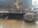
I can identify this wear if you post a side profile picture of the top of the coupler plate.
Jeffrey Bandel
Senior Member
Great. I'll post it up in the morning.I can identify this wear if you post a side profile picture of the top of the coupler plate.
Jeffrey Bandel
Senior Member
Here it is.Great. I'll post it up in the morning.

Jeffrey Bandel
Senior Member
Other side.
Jeffrey Bandel
Senior Member
My pins look ok. Fully locked down they are a little over an inch. Is that about right?
Tree Mulcher
Well-Known Member
Congratulations you have wear. The angled area on top should be taller. When new the angled area is tall enough that it runs across the full thickness of the plate I believe.
Make a template of the angle. None of the slope angles should be changed. Weld build up and grind to profile. My guess is you need to add close to 3/8 of an inch in height.
Hook up to a good attachment push on ground and measure the gap between the top of the coupler plate and the attachment. This should confirm about how much build up you need. Not all attachments have the same fit. You may want to check with multiple attachments.
If you need to find a new machine and make a templet to better understand do so. Maybe you can get a member to post a profile pic same as you did for a new machine to show the difference.
Make sure to preheat and keep the plate hot while welding to prevent warpage followed by post heating to get even cooling.
I preheated to 200F and kept Interpass to 300F. I used 7018 5/16 and 3/16 rod with success.
I welded a piece of flat bar across the front to help with warping during welding.
I may have wrapped the plate in home house rolled insulation to get even cooling after welding and post weld heating. All done while still attached to machine.
FYI bobcat machines do not wear in this area at all. I have welded cracks on bobcat couplers plates though in extreme applications.
I can't remember for sure.
Don't forget to disconnect battery before welding.
Last edited:
digger doug
Senior Member
I posted a link to the correct dimensions, easy to simply make a cardboard template with a protractorCongratulations you have wear. The angled area on top should be taller. When new the angled area is tall enough that it runs across the full thickness of the plate I believe.
Make a template of the angle. None of the slope angles should be changed. Weld build up and grind to profile. My guess is you need to add close to 3/8 of an inch in height.
Hook up to a good attachment push on ground and measure the gap between the top of the coupler plate and the attachment. This should confirm about how much build up you need. Not all attachments have the same fit. You may want to check with multiple attachments.
If you need to find a new machine and make a templet to better understand do so. Maybe you can get a member to post a profile pic same as you did for a new machine to show the difference.
Make sure to preheat and keep the plate hot while welding to prevent warpage followed by post heating to get even cooling.
I preheated to 200F and kept Interpass to 300F. I used 7018 5/16 and 3/16 rod with success.
I welded a piece of flat bar across the front to help with warping during welding.
I may have wrapped the plate in home house rolled insulation to get even cooling after welding and post weld heating. All done while still attached to machine.
FYI bobcat machines do not wear in this area at all. I have welded cracks on bobcat couplers plates though in extreme applications.
I can't remember for sure.
Don't forget to disconnect battery before welding.
and square.
If you copy from a new machine, you still don't now where in the tolerance band that was made.
The linked shows the complete over & under.
EDIT: My neighboring weld shop started making QC plates....."We measured one we got from a Bobcat".
And all 3 I bought from them are loose.
I'll wager that machine/bucket they copied was at the top end of the tolerance band, and they vary a wee bit more + & - as they build them.
So many (or all of them) that they build are too high, and are loose.
Last edited:
Jeffrey Bandel
Senior Member
I keep staring at that drawing. I get more confused the longer I look at it.
Jeffrey Bandel
Senior Member
Is there a drawing for the CAT mounting plate--not the implement? I can probably do the cardboard template but it would be easier if there was a drawing already done.
Jeffrey Bandel
Senior Member
I talked to CAT. Their drawing says the top angle is 40 degrees. The length is 353.7mm from the top of the top angle to the center of the pin--squared to the side of the plate.
Jeffrey Bandel
Senior Member
It looks like I have 3/16 inches of wear to build up. Not as much as I thought.