• Thank you for visiting HeavyEquipmentForums.com! Our objective is to provide industry professionals a place to gather to exchange questions, answers and ideas. We welcome you to register using the "Register" icon at the top of the page. We'd appreciate any help you can offer in spreading the word of our new site. The more members that join, the bigger resource for all to enjoy. Thank you!

Can’t find 289c hydraulic aux specs

Drago663

Member
Joined
Jan 15, 2022
Messages
18
Location
Ct
Trying to find specs for the flow of the third hydraulic hookup on my 189c.
I would have thought this would be a simple spec to find, but I have had no luck.

My 289c has:
high flow 33 gal/ min hookup
Reg flow 22 gal/ min hookup
And an extra aux hydraulic hookup that I can’t find spec of.

I can’t seem to find an answer anywhere about it, my first thought is maybe it’s simply the low flow of 22 gal/ min, but the hookups seem significantly smaller.

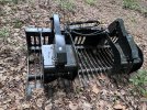
I’m looking for the expected flow of the aux hydraulic hookup because Im trying to spec a hydraulic vibrator for a rock bucket. To vibrate the dirt out and leave the rocks without having to shake the bucket back and fourth…

But also for other attachments it would be nice to know.

Any help is much appreciated!
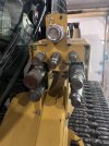
IMG_9218.jpegIMG_9205.jpeg
 

Drago663

Member
Joined
Jan 15, 2022
Messages
18
Location
Ct
Hi Nige,
Thanks again for helping!

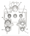
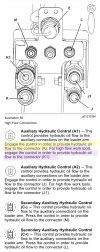
The pic below is the only place I could find mention in manual I have, I read it as reg flow for K and J, then high flow for K1 and J1

Then it simply says hydraulic flow to M and L

That’s why I thought if k and j was 22 gal and k1 and J1 are 32 gal, then the aux would be different… but I don’t know for sure, that’s why I was trying to figure it out.

I guess it might make sense that it’s reg flow, it’s just so much smaller than K and J, thought it had to be less.


IMG_9238.jpeg
 

Nige

Senior Member
Joined
Jun 22, 2011
Messages
29,297
Location
G..G..G..Granville.........!! Fetch your cloth.
The O&M Manual is not as clear as it could be, that's for sure.

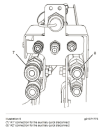
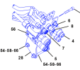
The most relvant information actually comes from a section in the Test & Adjust part of the Service Manual for the "High Flow hydraulic System". It uses a slightly differently labelled illustration than the one in the O&M. For context I repeat it below.

Step 7 of the test procedure states - "Install a jumper hose between the auxiliary quick disconnect coupling (7) and the auxiliary quick disconnect coupling (8). These couplings are located on the left hand side of the lift arms."
1686322636220.png
 

Nige

Senior Member
Joined
Jun 22, 2011
Messages
29,297
Location
G..G..G..Granville.........!! Fetch your cloth.
Should have looked at the hydraulic schematic first....!!

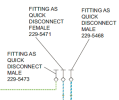
229-5468 is #6, 229-5471 is #7, & 229-5473 (case drain connection) is #8. These are the Std Flow connections. They are arrangeed slightly different on the machine because the case drain is in the centre.

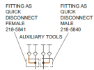
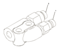
218-5840 is #4, 218-5841 is #5. These are the High Flow connections, the only difference between the two is the size of the coupling. Dig into each one in detail and it is a manifold with one inlet and two outlets. I have illustrated the 218-5840.


1686335237514.png1686335266431.png
1686335369421.png1686336189209.png
 

Drago663

Member
Joined
Jan 15, 2022
Messages
18
Location
Ct
That is exactly the info I was looking for, and you answered the next question I had about the manifold. At first glance it looks like it just splits one inlet to two outlets. Wasn’t sure if there was some type of priority valve in there or something… thank you!
 
Top