• Thank you for visiting HeavyEquipmentForums.com! Our objective is to provide industry professionals a place to gather to exchange questions, answers and ideas. We welcome you to register using the "Register" icon at the top of the page. We'd appreciate any help you can offer in spreading the word of our new site. The more members that join, the bigger resource for all to enjoy. Thank you!

Engine speed sensor code

AO299D

Well-Known Member
Joined
Nov 14, 2019
Messages
52
Location
Ontario
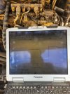
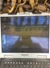
Hello I have a engine that brings up code 190-8 since it was rebuilt I put a new senser on and that didn't help attached are some graphes that might be helpful

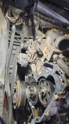
It's on a cat TL1055 telehandler
S\N TBM00416

Engine number is 292-5307

Might it be a grounding issue?
 

Attachments

  • 20230523_163854.jpg
    20230523_163854.jpg
    1.8 MB · Views: 12
  • 20230523_163819.jpg
    20230523_163819.jpg
    1.7 MB · Views: 12
  • 20230523_161202.jpg
    20230523_161202.jpg
    2.1 MB · Views: 12

Mechanicsville804

Well-Known Member
Joined
Dec 14, 2021
Messages
116
Location
Virginia
Have you tried to pull the sensor out and pass a metal object in front of it while watching the graph? If the sensor works well you could check to see if the sensor is too far away from the crankshaft gear and is not getting good detection of the gear.
 

AO299D

Well-Known Member
Joined
Nov 14, 2019
Messages
52
Location
Ontario
Finally working on this project again and found this out 1 tooth what is the process to time the middle idler to the crank shaft?
 

Attachments

  • IMG-20230614-WA0030.jpg
    IMG-20230614-WA0030.jpg
    337.3 KB · Views: 17

AO299D

Well-Known Member
Joined
Nov 14, 2019
Messages
52
Location
Ontario
Would you also have the file, Disassembly and Assembly, "Fuel Injection Pump Gear - Install"
 

Nige

Senior Member
Joined
Jun 22, 2011
Messages
29,314
Location
G..G..G..Granville.........!! Fetch your cloth.
Sorry about the formatting but it was the best I could do on a phone. I think you might struggle because the procedure calls for the pump to be locked and I assume yours isn’t…..
 

Attachments

  • FIP gear install.pdf
    194.6 KB · Views: 4
  • FIP installation.pdf
    241.6 KB · Views: 2

AO299D

Well-Known Member
Joined
Nov 14, 2019
Messages
52
Location
Ontario
I don't have the tool to lock no, can make out what this picture is show it looks like it might be another way of checking the timing in fuel pump.
 

Attachments

  • IMG_20230623_185818.jpg
    IMG_20230623_185818.jpg
    103.4 KB · Views: 4
  • IMG_20230623_185812.jpg
    IMG_20230623_185812.jpg
    117.1 KB · Views: 4

AO299D

Well-Known Member
Joined
Nov 14, 2019
Messages
52
Location
Ontario
I still havent been able to figure this one out it has to be either ecm, harness, sensor or engine its self
Are you sure nige that you posted the correct speed timing test my primary and secondary sensor are the same (2wire) and different locations then the diagrams any heres where im at

replaced the sensor
got the injection pump locking tool and varified timing
took oil pan off and inspected the teeth that go past the sensor
voltage at speed sensor plug is 7.9 v dc is this correct?
is there any device it could use the check the signal coming from the sensor?
there was no volt dc or ac or Hz when i checked sensor
should i maybe back probe at sensor with plug plugged in?
 

Nige

Senior Member
Joined
Jun 22, 2011
Messages
29,314
Location
G..G..G..Granville.........!! Fetch your cloth.
should i maybe back probe at sensor with plug plugged in?
All tests of sensors, etc, are backprobed with all connectors plugged in unless stated otherwise in the test procedure.

Your question regarding 2-wire vs 3-wire sensors got me thinking so I looked somewhere else.
You posted a 292-5307 number for the engine. That's the arrangement number, what is the Serial Number.? If I'm right I think it should be something like 444, 446, or 448xxxxx.

EDIT: I found this speed/timing sensor test that shows both primary and secondary sensors as being 2-wire.
 

Attachments

  • M0153279 Speed_Timing Test.pdf
    1.1 MB · Views: 2
Last edited:

Mechanicsville804

Well-Known Member
Joined
Dec 14, 2021
Messages
116
Location
Virginia
I still havent been able to figure this one out it has to be either ecm, harness, sensor or engine its self
Are you sure nige that you posted the correct speed timing test my primary and secondary sensor are the same (2wire) and different locations then the diagrams any heres where im at

replaced the sensor
got the injection pump locking tool and varified timing
took oil pan off and inspected the teeth that go past the sensor
voltage at speed sensor plug is 7.9 v dc is this correct?
is there any device it could use the check the signal coming from the sensor?
there was no volt dc or ac or Hz when i checked sensor
should i maybe back probe at sensor with plug plugged in

To test the sensor, you can back probe the plug using a sharpened paper clip and a volt meter and then pass a metal object ( a screw driver) in front of the sensor and see if the voltage goes up and down on your volt meter, this would prove your sensor is good. Is your spacing between your sensor and the gear correct?
 

Nige

Senior Member
Joined
Jun 22, 2011
Messages
29,314
Location
G..G..G..Granville.........!! Fetch your cloth.
To test the sensor, you can back probe the plug using a sharpened paper clip and a volt meter and then pass a metal object ( a screw driver) in front of the sensor and see if the voltage goes up and down on your volt meter, this would prove your sensor is good.
Or you could use a pukka set of backprobe spoons that TBH any half-decent tech should have in the case with his DMM.
 

Mechanicsville804

Well-Known Member
Joined
Dec 14, 2021
Messages
116
Location
Virginia
I'm not sure the specifics for your vehicle, but I can ask a few questions to try to help you. On the sensor is there an adjusting screw that will allow the sensor to get closer and further from the tooth of the gear? Is this an aftermarket sensor (possibly made with too much distance between the sensor and the gear tooth or just a weaker magnet that can pick up the signal)? You can also test the distance of how far your sensor can read by doing the back probe test and have a ruler on the table and see how far you can get before your sensor stops reading the metal object in front of it.
 

Bob Fos

Member
Joined
Jun 1, 2022
Messages
10
Location
Everett ontario
Hello everyone.
I am wondering if anyone can shed some light on this topic so we can get a end result.
So motor has been taken apart a few times now to try to diagnose.

1st.
Sensor throws error code for crank position sensor and unit is in derate.
When disconnecting sensor unit will run and throw code.
When sensor is installed.
It is picking up a signal.
I have 8 volts key on engine running with sensor back probed.
When watching primary and secondary second it jumps and looses signal.
When installing sensor with it backed off with 1 oring. It will pick up a signal and it causes engine to blow black/grey smoke.
And shut down engine and cause a crank no start.
When running unit it blows a good amount of grey smoke smells like advanced timing.
Would you invest the time into retiming it for a 3rd time.

New sensor.
Checked all wiring.
It's been down for 3 months. And customer wants it running he gave me this thread to view what he has done.
I belive from the smoke to the advanced timing smell plus smoke. It's bad timing.
And when the sensor.is hooked up it states basically bad timing done run.

Any advice.
 

Mechanicsville804

Well-Known Member
Joined
Dec 14, 2021
Messages
116
Location
Virginia
I re read the whole thread this morning and I saw something I didnt see earlier in post number four; is the injector pump gear off a tooth? Is the front cover off and can you put the engine in TDC and post a pic straight on so we can see all of the timing marks?
 
Top