• Thank you for visiting HeavyEquipmentForums.com! Our objective is to provide industry professionals a place to gather to exchange questions, answers and ideas. We welcome you to register using the "Register" icon at the top of the page. We'd appreciate any help you can offer in spreading the word of our new site. The more members that join, the bigger resource for all to enjoy. Thank you!

Ingersoll-Rand SD-100F Pro-Pac

Tony Wells

Senior Member
Joined
Jul 18, 2019
Messages
647
Location
Tyler, TX
Occupation
HogZilla Keeper
Hi Guys,
Got a wee bit of a problem. A hacked up electrical system. Really need a schematic to sort it out in the time-frame I've been asked to do it in.

Here's the tag:
IMG_1361.JPG


If anyone can help with a schematic, I'd sure appreciate it.
 

Tony Wells

Senior Member
Joined
Jul 18, 2019
Messages
647
Location
Tyler, TX
Occupation
HogZilla Keeper
Mainly cannot activate the vibrator motor, but there are no safety devices in use. No seat belt switch, no "neutral start" switch (will crank and take off), no back up beeper, and who knows what else. Lots of loose, some hot, wires in the thankfully plastic console. Some of the instruments have been replaced with aftermarket/generic gauges which probably caused some rewiring that left unused wires loose. The control for the vibrator speed is incorrect. The pot that sweeps the speed has both outer ends tied together so that the wiper can only read a single value. It's the 1k pot under the main knob. Judging by the soldering job, obviously not factory. At least the majority of the wire markers are still there, except for the added wires spliced in. Color and wire gauge changes at splice points. Key switch subbed in rather than push-button.

The machine will start and run normally, so no engine related problems, but not so sure about the pump/vibe motor circuit. Solenoid clicks with power applied, but don't know if it is actually opening. Have a flow meter on order but it will be slow getting here. At this point, can't get it to vibrate, but it could be the amplitude/frequency controls for all I know.
 

murfdog

Well-Known Member
Joined
Apr 7, 2013
Messages
54
Location
montana
I had the same problem with my sd25 and finally found that there was a rub short in the wiring from the vibrate/ forward reverse console
 

Tony Wells

Senior Member
Joined
Jul 18, 2019
Messages
647
Location
Tyler, TX
Occupation
HogZilla Keeper
murfdog, presently, I have that console all opened up and spread out. I found no accidental damage anywhere, just butchery. I've got the schematic now, so it's game on trying to put back what I can with what's left of the controls. If I can just get everyone to leave me alone with it, I can get it functional, provided there isn't a mechanical problem with the pump or vibe motor. As always, time is not on my side. The machine, actually one of two (other one is a Hamm, German mfg packer) that is in about the same shape electrically, but AFAIK, it doesn't have hydraulic problems. The turbo was ready to explode, and pumping about a pint a minute out the exhaust. New turbo arrived yesterday but wrong gasket and stud kit. The dash is all apart, so it might have some electrical issues but I haven't looked it yet. Someone else is on that one. Maybe we can get one out of two rushed out.

Anyone see anything wrong with this pic?
IMG_1363.JPG
 

Tony Wells

Senior Member
Joined
Jul 18, 2019
Messages
647
Location
Tyler, TX
Occupation
HogZilla Keeper
Apparently the schematic I have (in the op/maint manual) is incorrect for this serial number. It states that it starts at a sn significantly than my machine. They made quite a few changes so this schematic is pretty much useless. Oh well....on with the hunt.
 

Tony Wells

Senior Member
Joined
Jul 18, 2019
Messages
647
Location
Tyler, TX
Occupation
HogZilla Keeper
End of story: Vibratory pump had damaged valve plate, so had it rebuilt. That pump has a pilot control valve that is electrically actuated. Single coil style that can be driven by PWM signal (up to around 120 PPM i am told) or current control. Someone had opened it up and discarded one of the balance springs and dumped the silicone colling/damping fluid. Finally got to an engineer at Danfoss who was willing to tell me what should be there to drive that valve. That drive module was missing, so I designed a simple circuit that was simply a voltage divider and wirewound pot to control the dropped current to required values. It takes about 14 ma to move the valve off it's home position and about 90-100 ma to max it out. If you run across this, DO NOT simply shoot 12 VDC to the coil. It will move the valve to max, obviously, but will draw way too much current and I imagine burn the coil up pretty quickly. I think by calculation this circuit runs about 2.5-3 volts DC if you drive it like I did. I opted not to bother with building a PWM supply since I could get what I needed with DC.
I works, and is out to the job. I don't see how people tolerate running these things all day. I have a bad back, but a few minutes is all I could take running with vibration on max.
 

RPRZEN

Member
Joined
Aug 27, 2020
Messages
16
Location
Charlotte, Texas
Occupation
OILFIELD, CONSTRUCTION, RANCH EQUIPMENT TECHNICIAN
I am currently diagnosing an electrical issue on an IR SD 100F TF roller. PIN 194500. Does anyone have an electrical schematic?
 
Joined
Jun 1, 2021
Messages
6
Location
Washington
Tony I am having the EXACT same problems with a similar machine it is an SD100D. Can you post pictures of your repair? Could you send me a picture of your wiring diagram?
 

Tony Wells

Senior Member
Joined
Jul 18, 2019
Messages
647
Location
Tyler, TX
Occupation
HogZilla Keeper
Tony I am having the EXACT same problems with a similar machine it is an SD100D. Can you post pictures of your repair? Could you send me a picture of your wiring diagram?


I'm sure I kept a sketch of the circuit. I'll dig through the piles on the desk and electronics bench and see. If not, I'll do the calculations again. It wasn't that difficult. Can you post a pic of the pilot control valve? I'd like to see the one on your machine just for reference. I'd hate to help you fry yours. A pic of the existing control panel from the underside wouldn't hurt either.
 
Joined
Jun 1, 2021
Messages
6
Location
Washington
Thank you for the reply! I just bought a set of books from our nearest volvo dealership however they were for a volvo SD100D not an IR SD100D so I am back to trying to make it work until I can track down the right parts.
 

Attachments

  • 20210601_090756.jpg
    20210601_090756.jpg
    1.5 MB · Views: 16
  • 20210601_090847.jpg
    20210601_090847.jpg
    1.7 MB · Views: 14

Tony Wells

Senior Member
Joined
Jul 18, 2019
Messages
647
Location
Tyler, TX
Occupation
HogZilla Keeper
Did your machine have a high and low amplitude switch?

It did, but I decided to just give only the entire speed range of the pilot valve with the potentiometer. It was missing anyway. No complaints back from the operators. The only thing I would add, which I didn't have on hand quick enough is a simple on/off switch. It could be a toggle or push-on/push-off....whatever you have. I ran the risk of having the machine start with the vibrator running. The switch won't eliminate that risk, but if you want to take the time you could put a relay and idiot lamp in there to at least let the op know the vib is active when they turn the key on. Or you could design an interlock where it wouldn't start if it was active. I just had about 2 hours when it came down to it so I couldn't make it all fancy and foolproof.

Here's what I built. Best I remember. I found some rough drafts but not the finished design, but that's how I recall building it. There's a possibility that the 5 watt primary dropping resistor should be ~100 Ω instead of 47 Ω. I remember trying both and I believe the current range was "safer" for the solenoid coil with a greater initial drop. There is a sacrifice in ultimate range and speed, but finer control. Too many projects under the bridge. Tomorrow I'll run all the numbers again to be sure, if you just have one shot at it, or just have to turn this over to someone else to build.
I pulled two new wires from the solenoid back to the dash box because it was pretty butchered up and I wanted fresh isolated wire and good connections. 16-18g is sufficient. This less than 200 ma current at the solenoid. It might be wise to check the DC resistance of your coil. There were some variations built. If it's not close to mine (22.4 Ω), let me know.

Forgive the sloppy sketch, I have only half a thumb on my writing hand and don't hold a pen too steady.
IMG_2763.JPG
 
Joined
Jun 1, 2021
Messages
6
Location
Washington
Okay so mine is a little more complete than yours was, it has a push on/off button in the travel handle and the vibe controls were all there just not wired properly, there are two POTs and a 56ohm resistor. The upper POT is for the operator to adjust the VPM and a high low amplitude switch which I think may reverse the polarity to the coil, I could be wrong but the pilot solenoid has a little plastic lever on it and you can move it manually forward and backwards to make the vibe activate. The lower POT according to the operators manual is for adjusting the low speed, so trimming the voltage to the upper pot is my guess. The say the high speed is set by engine rpm. I believe I just need a new switch and POT and I may be okay. The machine harness just had a couple rubbed thru spots and then someone bypassed it and had ran 90 miles of wire to it to make everything work. So i pulled the harness removed the jacket and replaced some wires and connectors and put it back and was having intermittent vibe control which i think was the POT looks like it was turned all the way around and the switch broke on me when I tried to pull some connectors for testing.
 
Joined
Jun 1, 2021
Messages
6
Location
Washington
Also I cut out the side of the plastic control box and made a cover, it makes it so much easier to access the wiring and the travel lever linkage
 

Attachments

  • 20210602_084145.jpg
    20210602_084145.jpg
    1.8 MB · Views: 10

Tony Wells

Senior Member
Joined
Jul 18, 2019
Messages
647
Location
Tyler, TX
Occupation
HogZilla Keeper
The lever on the side of the pilot valve is to manually test the internal workings of the valve, according to the mfg I spoke with. If you have the main original harness, I'd think you'd be better off trying to repair it. Most everything on mine was ripped out already so I had no choice but to find out what signal was required to drive that pilot and then figure out a way to supply it. It is supposed to be reversible electrically, but I spoke with our operators and they said they didn't care, it really didn't need to be for their use. I just chose a DC current control over a PWM fixed voltage power supply. That's what mine boiled down to.

I'd recommend a wirewound pot for sure though, for longevity, even if you can't find one with a back mounted switch.

Have fun!
 

03hdrk

Well-Known Member
Joined
Aug 28, 2015
Messages
127
Location
N TX
I know this is a year old, but I just came accross this post looking for a parts manual for a SD105TF. I have a little experience with these machines. If Tony and or Spencer are still following - reply and I will give some insite on the amplitude hi/lo function.
 

Tony Wells

Senior Member
Joined
Jul 18, 2019
Messages
647
Location
Tyler, TX
Occupation
HogZilla Keeper
For my part, the problem is solved. My solution is still working satisfactorily. I sent the machine to Alabama and it's been in service since. I don't know how much they really use it, but I've heard nothing but good about it. I appreciate the follow-up though.

Spencer will probably chime in on his machine.
 

03hdrk

Well-Known Member
Joined
Aug 28, 2015
Messages
127
Location
N TX
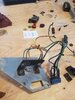
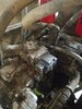
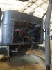
From reading the post, it sounds like you guys are really qualified mechanics and I don't want to come accross as a "know it all". Also did not want to try to help if no one was listening. From what I have read here, you two mentioned the amplitude circuit breifly and somewhere mentioned that you though it changed polarity of the circuit(I am not good at putting quotes in threads). I just wanted to let both of you know (in case you didn't) that the amplitude switch changes the direction of the hydraulic motor that spins the eccentric weights that make the drum vibrate. So there is (at least on the ones I have worked on) a 3 way valve - thumb button on FNR lever turns off - high amplitude switch postition should pull valve one way when energized, and on low pulls the other side of the valve. There are 2 weights on the shaft in large housings on each side of the drum, running in gear oil. 1 wieight is keyed to the shaft, the other can move about 100 degrees (maybe less - it has been a long time since I went into one of these). In the low amplitude direction the moving weight spreads away from the keyed weight and comes close to balancing the assembly, thus it has a lower up and down motion - kind of like a tire that is mildly out of balance. In the Hi amplitude rotation direction, the wieghts stay together creating one big weight thus shaking the machine way more violently.
The first one I worked on had the full operators manual and the information in there, regarding properly compacting soil and soil types, is very extensive. Yet I have talked to experienced road building supervisors who only know - wet it, grade it, pack it, grade it, pave it. There are places around here where new paving jobs have speed bumps in them because the guy running the vibratory compactor was on high amplitude when he should have been on low, and everytime he switched direction, he over compacted a spot in the subgrade. Running on high on already compacted surfaces is probably the main reason these machines get shaken to peices.

Just thought I would try to help since there are probably very few people who get to rebuild one of these drums and see what they do. Hope I did not insult anyone's intelligence.

BTW the reason I rebuilt the drum was because the old dirt contractor bought a SD120D to pack key trenches in tank dams, installed pad foot plates on the smooth wheel and went to climbing in an out of a short but 40 ft deep trench in wet clay. The operator said it kind of stalled out one time going up the grade and never really climbed as good after that. The complaint years later was that the machines tires would loose traction on the least incline. I was green, and took some bad advice from a dealer technician and had the drum drive motor reman at a hydraulic shop. Did not change a thing. Then the same technicion said must be a bearing problem in the main drum bearings - that is what is causing the drum to seemingly bind up and make the back wheels spin out. So I pulled the drum and figured reseal everything since we have it tore down this far. So I got to go into the weight cases and drive system. It was a pretty involved job by myself. While I had the torque hub planetary off (the one the drive motor is attached to) I went to change the oil in it and found mostly metal - it was like a coffee grinder on the inside. Don't know why I followed that guy's direction, all I had to do was drain the oil in the torque hub and found the metal. What I learned was that the "D" models are made for smooth wheel and have a much smaller torque hub, the "F" has a larger torque hub and is made for pad feet. I replace the torque hub with and "F" model hub and had to replace the plate it mounts to as well. We compared part numbers to every relavant hydrualic component to make sure the "F" model did not need more parts, which it didn't and as far as I know he still has that machine today (this was in about 2011).
 
Joined
Jun 1, 2021
Messages
6
Location
Washington
I did know about the vibe pump changing its direction on flow for hi-lo amplitude but i didnt know about the weights but that makes sense to me. The roller I was working on is working okay for now but I know its not exactly right because we also have a sd110d roller and its vibe system hasnt been hacked and works perfectly fine and has more adjustability Id say. Thanks for the extra info thats always helpful.
 
Top