• Thank you for visiting HeavyEquipmentForums.com! Our objective is to provide industry professionals a place to gather to exchange questions, answers and ideas. We welcome you to register using the "Register" icon at the top of the page. We'd appreciate any help you can offer in spreading the word of our new site. The more members that join, the bigger resource for all to enjoy. Thank you!

Makers Acres

Well-Known Member
Joined
Sep 13, 2020
Messages
202
Location
Los Angeles, California
Occupation
Imagineer
Hey all, Just curious if anyone knows if there is a site like this but for scissor lifts? Maybe it is buried here somewhere and I can't find it here?

I am trying to work on a JLG 2033e Lift and need some detailed information I can't find about the controller and trying to find some help.

Thanks!
 

Pete w

Well-Known Member
Joined
Jul 6, 2020
Messages
93
Location
OH
Not sure how much detail you are looking for, but have you called JLG? I rebuilt and wired a man lift not long ago. They sent me the service manual no questions asked. But it was your basic wiring schematics and all, so depends on your depth of detail.
 

Jeff14889

Active Member
Joined
Aug 26, 2020
Messages
30
Location
New york
Go to jlg.s website and you can download the service manuals for them. As far as the controller, it depends on what the serial number is the older ones had a ckt board in the ground control box that held all the programming, the newer ones that was integrated into the motor controller. The manuals will give tell you how to test them with an ohm meter but nothing really in-depth. What the issue your having?
 

Makers Acres

Well-Known Member
Joined
Sep 13, 2020
Messages
202
Location
Los Angeles, California
Occupation
Imagineer
Ya. I have pulled the manuals and disassembled the control board and found the bad component. It was however too damaged to recognize the part number. If I can get a part number, I can replace the part myself.
 

Attachments

  • 1CA42CCE-9D0F-4D6A-8327-BC5AC8F8969C.jpeg
    1CA42CCE-9D0F-4D6A-8327-BC5AC8F8969C.jpeg
    1.8 MB · Views: 38
  • 481F2613-677B-48D2-83E7-3B201072ED3B.jpeg
    481F2613-677B-48D2-83E7-3B201072ED3B.jpeg
    1.4 MB · Views: 34

Jeff14889

Active Member
Joined
Aug 26, 2020
Messages
30
Location
New york
You won’t be able to get individual diodes or transistors from jlg for the board, would have to get the whole board assembly. The board looks damaged too anyway.
 

Makers Acres

Well-Known Member
Joined
Sep 13, 2020
Messages
202
Location
Los Angeles, California
Occupation
Imagineer
You won’t be able to get individual diodes or transistors from jlg for the board, would have to get the whole board assembly. The board looks damaged too anyway.
I cleaned the board off and removed the part. The board is in great shape, it was just the conformal coating that was damaged due to heat it looks like. Yes, I am well aware that you don't get those kind of parts from them. I'm just trying to find someone who knows what that part number is so I can order one from Digit-Key or Mouser.
 

Makers Acres

Well-Known Member
Joined
Sep 13, 2020
Messages
202
Location
Los Angeles, California
Occupation
Imagineer
Not sure how much detail you are looking for, but have you called JLG? I rebuilt and wired a man lift not long ago. They sent me the service manual no questions asked. But it was your basic wiring schematics and all, so depends on your depth of detail.
Thanks. I did find the service manual but the schematics are not detailed enough. JLG said they outsourced the board design and they don't have a parts diagram.
 

Makers Acres

Well-Known Member
Joined
Sep 13, 2020
Messages
202
Location
Los Angeles, California
Occupation
Imagineer
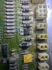
Alright, just to give a bit of an update. I bought another dead controller from ebay, being sold “as parts”. The owner thought it mostly worked, but the power extension no longer functioned. I don't have power extension on my lift, so I thought I might have a good shot here...

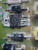
However, I was disappointed once I opened the unit and found the exact same part had exploded on the board, as on my controller!
Once again I could see no part numbers on the dead component.
This must be a common problem with these boards! So I set this aside for a couple of days, ruminated, and then the most awesome thing happened! I took it outside to show someone, and by chance the sunlight reflected off it in a way that I got a small outline of a part number. HOLY COW!!!! Very exciting.

I was able to read “VN31” from the remaining half of the board still intact. After doing some research, this was a part that was previously made by STMicroelectronics. It is a discontinued part these days, but you can still find people that have these chips.

It appears this chip hasn't been made for 10plus years. Now I didn't want to just replace this with the same one as I feared this part might be a ticking time bomb. However, I did a lot of research and came across a component that appears to be better in every way:

The New component is “BTS441RS”, made by Infineon Technologies.

I compared the spec sheets of both the old and the new component, and it has a couple of key things that I think made it way better.

#1 - Protection Circuitry - This new component has an internal protection Diode. My electronics friends think this component is most likely failing due to back driving EMF which might be caused by the contractor when it disengages. The Control board does have some protection Diodes that are supposed to handle this, but after closer inspection they are not the correct type that the Datasheet called for for VN31.

#2 - Efficiency - This part is about half the resistance as the previous component, which means it is more efficient and will produce less heat. This is great since these components are typically attached to a large heat sink. In this case, it is just bolted to the fiberglass motherboard which doesn’t allow for efficient heat removal. Now I understand this component is not being driven to its full potential, so the heat should be small anyways, but still; less heat = good.

#3 - Availability - This part is currently in production which bodes well for it being around for a while. I am just guessing here, but the other manufacturer stopped making these series of chips completely, which leads me to believe there may have been a known issue with this component.

Anyhow, once I have the new chip, I will install it and post another update.

Thanks for following along!

Also, just to add to make this post easier to find, I am talking about the JLG controller 1600286 and the component on the board is labeled as Q31.
 
Last edited:

Makers Acres

Well-Known Member
Joined
Sep 13, 2020
Messages
202
Location
Los Angeles, California
Occupation
Imagineer
***UPDATE***

So here is an update. I received the part and installed it, and it still didn’t work. I was pretty disappointed, back to more troubleshooting.

I looked at the control wire to the new chip and traced it back to the main CPU. It appeared to be dead, and I never really saw any signal coming from it. I decided to remove the control pin from the board, and I drove it with an external 5V power supply.

BINGO! The flasher came on and I heard the buzzer. I could now drive the motor and normal functions. Now the bad news: this means the Main CPU Pin blew when this chip blew. UGH!

After doing some research, I found they still make these CPU’s, but in a new flavor that has built-in storage. The bad news is this original chip has no onboard storage, so I had to find someone who had stock of the original chip, without the storage. The good news is if we swap the chip, no programming is required. This is because all the storage lives on a separate, external storage-only chip.

I found someone on e-bay who had them and ordered a few. For reference, this is the exact part number you need:
HD6413003F16

It took a few weeks to get it, since it was coming from China. Once I received the Chip, I had my friend remove the old one (a very precise and intricate task) and install this one, since it is a surface-mount processor and can be tricky to do unless you have experience. Big shout out to my buddy Kevin! He worked on the Mars Rover and he was nice enough to spare me some time to do this tricky work for me.

So now the moment of truth…

I plugged in the new board and popped the e-stop and pushed the enable button on the hand controls, & the flasher started right up!
I push the control forward and it drove forward!!!

Whoohoo! Big win!

I took it all back out, and used some spray-on conformal coating (a special paint for circuit boards to protect them from the elements).

This whole process was about 9 months of frustration that ate at me, but finally success and it feels good that I solved it and now understand this machine better.

My hopes are to pass this knowledge on, to help someone in the future as these parts become harder and harder to find.
 

A. Williamson

Active Member
Joined
May 29, 2021
Messages
27
Location
USA
Really nice work, man. Was the board coated with something that you had to remove before desoldering the components?
 

A. Williamson

Active Member
Joined
May 29, 2021
Messages
27
Location
USA
Any ideas as to what caused the failure in the first place? I see you mentioned the "contractor" - is that like a contactor? I assume you don't mean the guy driving the machine lol. Something about a collapsing magnetic field sending current back to the chip? Is that the working theory?
 

Makers Acres

Well-Known Member
Joined
Sep 13, 2020
Messages
202
Location
Los Angeles, California
Occupation
Imagineer
Haha, yes, you are right. I was talking about the contactor.

So I have two working theories. The first one is that this manufacture made a bunch of these bad chips as this is no longer a chip they make, and this seems like on this board it is a common failure for this chip to blow up. My second theory from my buddy how knows a lot more about these chips. It is that low voltage is the enemy of these chips, especially the old one that they shipped with. As you get lower in voltage and try to switch on a load that is outside the operating range, this could cause the chip to overheat and fail like this. When it went, it probably bridged internally and sent that higher voltage down the 5v rail of the processor and took that out as well. The new chip I found has a lot more internal protections (including a diode between the control pin and the internal circuit) as well as runs a lot more efficiently.

This machine had the flasher connected incorrectly too. One side was wired to the the e-stop, and the other side wired directly to the first battery. So instead of switching on and off with the contactor, it would always flash when the e-stops were not engaged. So if you were not vigilant about pressing the e-stops, this would slowly drain the battery. This killed a lot of batteries in this machine and he constantly found the machine dead from his co-workers not pressing them when going home for the day. In this case since it was only wired to the first battery, it would only kill one 6v cell way past the low limit. So this would almost put the machine in a lower voltage state.

I am of course open to more suggestions.
 

Emmetthales

New Member
Joined
Nov 20, 2023
Messages
3
Location
Ireland
I have just purchased one of these machines as a non runner. With a 9-9 flashing code. I am pretty sure that the board is not working.
 

Emmetthales

New Member
Joined
Nov 20, 2023
Messages
3
Location
Ireland
Hi there, how are you.
I have sent the board away to a guy who knows them well and is used to fixing them but he has reported that is scrap as the main chip is gone. So I have sourced a new one in the UK for 550 pounds sterling but I must save up a few more weeks before I go ahead with it. It could be a few months yet before I get it going. I am still looking on ebay most days and Facebook market place to see if anything comes up. At least I know I can get one
 
Top