Good morning, I have an a35c that burned the transmission module, I am operating it in safe mode. but it only does the 2nd gear, I would like to know which of the terminals are responsible for the gear solenoids and what voltage stops them.

-
Thank you for visiting HeavyEquipmentForums.com! Our objective is to provide industry professionals a place to gather to exchange questions, answers and ideas. We welcome you to register using the "Register" icon at the top of the page. We'd appreciate any help you can offer in spreading the word of our new site. The more members that join, the bigger resource for all to enjoy. Thank you!
You are using an out of date browser. It may not display this or other websites correctly.
You should upgrade or use an alternative browser.
You should upgrade or use an alternative browser.
A35c - transmission - eletric problem
- Thread starter GuzBR123
- Start date
sfrs4
Senior Member
What's the serial number of your truck? so I can try to get the right wiring diagram.
funwithfuel
Senior Member
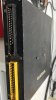
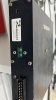
You know, there's not a lot of black magic and voodoo in there. That was an early (simple) ECU. Odds are someone under-protected the unit with a bigger fuse. Carefully remove the screws from both ends and the center. Slide the board out and look for a burnt trace. You can jump the burn section with telephone wire. If you don't trust your skills find an ol timer TV repairman to solder it for ya. Good luck. I also seem to recall a zener diode that would occasionally crap out as well. Again, good luck.

sfrs4
Senior Member
Hi Guz, take a look at the wiring diagram attached, unfortunately there are no voltage levels on the drawings
The following colours are used in wiring diagrams:
SB = Black
R = Red
GN = Green
BL = Blue
Y = Yellow
W = White
BN = Brown
GR = Grey
P = Pink
V = Violet
OR = Orange
The following colours are used in wiring diagrams:
SB = Black
R = Red
GN = Green
BL = Blue
Y = Yellow
W = White
BN = Brown
GR = Grey
P = Pink
V = Violet
OR = Orange
Attachments

sfrs4
Senior Member
where is that from? the attached is the wiring diagram for the correct A35C serial number range wiring, and none of that ties in with what you have there, the pins on the A and B plug start at 1to 7 on the left hand side 1 being the top with the rounded plug end, down to 7 on the flat bottom then 8 - 14 down the right side 8 at the rounded top 14 at the flat bottom
