
-
Thank you for visiting HeavyEquipmentForums.com! Our objective is to provide industry professionals a place to gather to exchange questions, answers and ideas. We welcome you to register using the "Register" icon at the top of the page. We'd appreciate any help you can offer in spreading the word of our new site. The more members that join, the bigger resource for all to enjoy. Thank you!
You are using an out of date browser. It may not display this or other websites correctly.
You should upgrade or use an alternative browser.
You should upgrade or use an alternative browser.
Auxiliary hydraulic circuit
- Thread starter Marksan
- Start date
Jam
Well-Known Member
Hows it going... You should see the auxilary splice on your valve chest. Psi will depend on what the last owner set the relief valve pressure at. You should see the two relief valves screwed into the splice. Fingers crossed you will have your pilot lines still in place
Hello Jam,
Ok, im mechanically inclined, but hydraulically inexperienced, so i might be a little 'slow' on the uptake
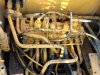
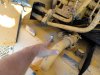
The hoe was plumbed for a hydraulic thumb by the P/O.ln the pictures im pointing at is a capped of fitting into the hydraulic tank, and a 'T' fitting that comes of off the swing motor hydraulic line.
ls this a way that people plumb into the system when there isnt a auxiliary system?
let me know if there any pics you need.
Cheers
Ok, im mechanically inclined, but hydraulically inexperienced, so i might be a little 'slow' on the uptake
The hoe was plumbed for a hydraulic thumb by the P/O.ln the pictures im pointing at is a capped of fitting into the hydraulic tank, and a 'T' fitting that comes of off the swing motor hydraulic line.
ls this a way that people plumb into the system when there isnt a auxiliary system?
let me know if there any pics you need.
Cheers
Attachments
Jam
Well-Known Member
Hey Mark
Looks like the p/o didnt leave you with much, you dont seem to have any additional valve splice on your chest for auxilary so it would have been plumbed as an ad-on. Are you sure thats a slew motor supply line with the t fitting, cant under stand why that would be used? Is there anything left on the control side, foot pedal, electric changeover,ect?
Looks like the p/o didnt leave you with much, you dont seem to have any additional valve splice on your chest for auxilary so it would have been plumbed as an ad-on. Are you sure thats a slew motor supply line with the t fitting, cant under stand why that would be used? Is there anything left on the control side, foot pedal, electric changeover,ect?
willie59
Administrator
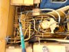
Whoa? What is that pipe sticking up in the lower left corner of pic #1? Is that the swing gearbox dipstick tube with no dipstick?
I agree Jam, don't look like there's much there for aux hydraulics. Gonna need some components I think.
I agree Jam, don't look like there's much there for aux hydraulics. Gonna need some components I think.
Whoa? What is that pipe sticking up in the lower left corner of pic #1? Is that the swing gearbox dipstick tube with no dipstick?
I agree Jam, don't look like there's much there for aux hydraulics. Gonna need some components I think.
NO!!!!!!!!!!!!!! Thats not a missing dipstick
willie59
Administrator
Ok.
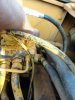
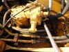
.....................here is a better pic. You can see the line that has been 'T'ed into and capped at the place pointed to by the pole, it goes into the swing motor where pointed in the second pic.
Theres nothing in the cab bar a (broken) switch ontop of joystick.
lve also emailed the P/O, to see if he can shed some light on it. However i dont know if hes still around as ive had the machine a few years.
Cheers
Theres nothing in the cab bar a (broken) switch ontop of joystick.
lve also emailed the P/O, to see if he can shed some light on it. However i dont know if hes still around as ive had the machine a few years.
Cheers
Attachments
Jam
Well-Known Member
Hey again mark that pipe is a return coming from the slew motor for when the relief valves open. It is going back to the manifold at the rear of your chest where it returns to the tank. My guess would be this was used for the same purpose with your auxilary piping in place
Hey again mark that pipe is a return coming from the slew motor for when the relief valves open. It is going back to the manifold at the rear of your chest where it returns to the tank. My guess would be this was used for the same purpose with your auxilary piping in place
Thanks Jam!
So if thats the return, where is the 'input' coming from, would it be that capped fitting on the tank? or is the tank not pressureised ??
Cheers
Jam
Well-Known Member
If you look back along your pump outlet lines youl prob see where the pressure side was taken off. Or it could have been taken off the end of your valve chest. Not really sure what the tank fitting is for but if you are going replumbing try not to use that and use the return manifold as this oil is return to the tank via a filter
Hi everyone!
On Kobelco mark 2 excavators the high flow auxiliary circuit is a closed center valve
connected to the right side of the main valve the same way as the swing valve is
connected to the left side of the main valve. On the first photo in post #8 you are pointing
at the return line from the swing valve. The return line from the auxiliary valve can be
connected there if it is used for thumb, rototilt, crusher etc, but not for a hydraulic hammer or a scrap shear. On the first photo in post #3 I belive I can see a plug on the right side of the main valve which is not a Kobelco original plug so probably the auxiliary circuit has been connected there. If a Kobelco mark 2 is originally fitted with a low flow auxiliary circuit, there is a flow divider fitted between both main pumps and the main valve connected to an external hydraulic valve. If you want to add an high flow auxiliary circuit it’s easy to do it and the result will be good if it’s properly done. However, you will need some parts.
Hi everyone!
On Kobelco mark 2 excavators the high flow auxiliary circuit is a closed center valve
connected to the right side of the main valve the same way as the swing valve is
connected to the left side of the main valve. On the first photo in post #8 you are pointing
at the return line from the swing valve. The return line from the auxiliary valve can be
connected there if it is used for thumb, rototilt, crusher etc, but not for a hydraulic hammer or a scrap shear. On the first photo in post #3 I belive I can see a plug on the right side of the main valve which is not a Kobelco original plug so probably the auxiliary circuit has been connected there. If a Kobelco mark 2 is originally fitted with a low flow auxiliary circuit, there is a flow divider fitted between both main pumps and the main valve connected to an external hydraulic valve. If you want to add an high flow auxiliary circuit it’s easy to do it and the result will be good if it’s properly done. However, you will need some parts.
Kjell, could to give me a little detail to which plug on the main valve you are refering to. ls it a low flow outlet, as i need 28gpm for this attachment?
Tack så mycket
Thanks
Last edited:
Thanks for all your input guys.
So, this is what we are going to do for the brushcutter.
The return will be plumbed into the swing motor return as seen in pic #2 of post #3 and pic #1 of post #8
The bypass line will be attached to the tank as seen in pic#3 of post #3.
Kjell, i hear you, the bypass line has its own inline filter, i may put the bypass return to the hyd tank cap on top of the filter, as it has a plugged fitting already there.
The input line with either be 'T'ed of of the drive input line (not moving while cutting) or attached to the head as Kjell suggests, pending examination, as the brushcutter needs 28gpm.
l will keep you posted.
If you follow the pressure hose from the swing valve on the swing motor to theKjell, could to give me a little detail to which plug on the main valve you are refering to. ls it a low flow outlet, as i need 28gpm for this attachment?
Tack så mycket
Thanks
left short side of the main valve and then look at the right short side of the main
valve you will see a big plug 3/4" or 1" in the same place as the swing hose is connected on the left side. The plug i think i can see is if i am right the POP1 plug where the servo signal from the auxiliary valve should be connected. This is a high flow outlet. The flow is 55gpm, pressure is 284 bar.
Thanks for all your input guys.
So, this is what we are going to do for the brushcutter.
The return will be plumbed into the swing motor return as seen in pic #2 of post #3 and pic #1 of post #8
The bypass line will be attached to the tank as seen in pic#3 of post #3.
Kjell, i hear you, the bypass line has its own inline filter, i may put the bypass return to the hyd tank cap on top of the filter, as it has a plugged fitting already there.
The input line with either be 'T'ed of of the drive input line (not moving while cutting) or attached to the head as Kjell suggests, pending examination, as the brushcutter needs 28gpm.
l will keep you posted.
Return and bypass lines are ok.If you connect to the pressure line between the main valve and a travelmotor i suggest an electric 3/2 valve (or 6/2 if you want a two way function) and you use the travelmotor which is supplied by pump number 2. If you use pump number 1, oil which not is used by the brushcutter will be supplied to the arm and the swing. If you use pump number 2 oil which not is used by the brushcutter will be supplied to the boom and the bucket. Arm,boom bucket and swing will allways be supplied by one pump. Max flow is 55 gpm max pressure is 343 bar. This solution is not as good as an auxiliary valve but will cost you less money.If you dont need a two way flow an electric flow divider between pump number 2 and and the main valve is a simple and inexpensive alterntive.
MR. KOBELCO
Resigned
- Joined
- Jul 31, 2008
- Messages
- 433
- Location
- CANADA
- Occupation
- PARTS & SERVICE MGR. AMOUNG OTHER HATS @ KOBELCO D
hey,
watch for a link tomorrow to download a servicemans handbook that will help you with
your plumbing as to the locations of porting to tap into and port to signal stroking on the hyd pump " pop1 "
pf 1/4" = jis bspp 1/4"
the hyd fittings you source to tap into the various ports would require oe kobelco o-rings. example for pf 1/4 port use part# zd12p01100