• Thank you for visiting HeavyEquipmentForums.com! Our objective is to provide industry professionals a place to gather to exchange questions, answers and ideas. We welcome you to register using the "Register" icon at the top of the page. We'd appreciate any help you can offer in spreading the word of our new site. The more members that join, the bigger resource for all to enjoy. Thank you!

CAT 257B Park Brake Stuck On

Anss1899

Member
Joined
Aug 5, 2024
Messages
10
Location
USA
I have a 257B CAT. SN SLK00874.

The park brake randomly seemed to stick on last night when using the machine. I can’t remember if it did it while driving it or just after pressing the “park” switch in the cab then going to move. Regardless, the park brake seems to be stuck. When I press the park switch, the park light goes out and I’m able to use the boom and bucket no problem, fast as usual. When I go to move the machine, the engine will load up like it’s under load but the machine won’t move. I can see both sides of the tracks try and move but it won’t go. I was able to move it a couple inches but I don’t want to be pushing it when the brake is on. Lap bar seems to function correctly. Fuses good. No other trouble lights, runs good and the other functions including aux seem to all activate.


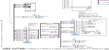
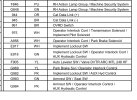
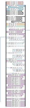
Does anyone know how the park brake solenoids work? Or any other leads? I read into the electrical schematic but I think I’m reading it wrong. Attached is what I see in the schematic. Is it a 12v wire and a ground I assume going to the solenoid?

Any help is appreciated. In the meantime I’m going to keep studying the schematic in prep for troubleshooting later. Thanks !
 

Attachments

  • IMG_7359.png
    IMG_7359.png
    708.8 KB · Views: 3
  • IMG_7357.jpeg
    IMG_7357.jpeg
    374.7 KB · Views: 3
  • IMG_7356.jpeg
    IMG_7356.jpeg
    312.6 KB · Views: 3

Nige

Senior Member
Joined
Jun 22, 2011
Messages
38,504
Location
G..G..G..Granville.........!! Fetch your cloth.
I read into the electrical schematic but I think I’m reading it wrong. Attached is what I see in the schematic. Is it a 12v wire and a ground I assume going to the solenoid?
The 2 wires for the parking brake solenoid both come from the Interlock Control.
A958 White connects to Pin 13 - marked PARKING BRAKE SOL.
G969 Yellow connects to Pin 66 - marked RELAY RETURN.

When the solenoid is energised to release the parking brake there should be system voltage when measured between Pins 13 & 66 on the Interlock Control with everything connected. You will have to backprobe the 70-pin connector at the control to measure that voltage. The same voltage should exist when measured between the pins of the 2-pin connector at the solenoid itself.

If you want to check the resistance of the coil in the parking brake solenoid valve the specification is 10 ± 0.5 ohms.
 

Anss1899

Member
Joined
Aug 5, 2024
Messages
10
Location
USA
The 2 wires for the parking brake solenoid both come from the Interlock Control.
A958 White connects to Pin 13 - marked PARKING BRAKE SOL.
G969 Yellow connects to Pin 66 - marked RELAY RETURN.

When the solenoid is energised to release the parking brake there should be system voltage when measured between Pins 13 & 66 on the Interlock Control with everything connected. You will have to backprobe the 70-pin connector at the control to measure that voltage. The same voltage should exist when measured between the pins of the 2-pin connector at the solenoid itself.

If you want to check the resistance of the coil in the parking brake solenoid valve the specification is 10 ± 0.5 ohms.
Excuse my dull understanding, thank you though for elaborating more on it. It’s making more sense. By control you mean the computer connector under the foot plate? And system voltage you mean 12v (nominal) or is the solenoid using some weird 4v voltage or something?

And I imagine pin 13 is my positive voltage while the relay return is the “common”? Strange why it wouldn’t just go to a ground instead of being more complicated.

I’ll definitely check the valve resistance as well, that should be easy. I imagine those are might be hard to find and expensive.

Hoping it’s just a broken wire or bad ground or something and not the dang interlock/computer thing.
 

Nige

Senior Member
Joined
Jun 22, 2011
Messages
38,504
Location
G..G..G..Granville.........!! Fetch your cloth.
By control you mean the computer connector under the foot plate? The actual voltage will dep
Yes indeed, although there are two of them. The one on the left side of the machine is the Interlock Control, the one on the right is the AUX Hydraulic Control. Attached the chassis wiring.
And system voltage you mean 12v (nominal)
Again yes. The actual voltage you measure will depend on what's in the battery at the time you test it.
And I imagine pin 13 is my positive voltage while the relay return is the “common”? Strange why it wouldn’t just go to a ground instead of being more complicated.
You are correct. For safety items such as braking systems it's not unusual to have them grounded back to the control rather than to some random point on the chassis that could suffer from corrosion. Speaking of corrosion inspect both controls under the floor and their connectors thoroughly and give them a good clean while you are in there.

Please can you confirm that the electrical schematic you are using is RENR6419-06. That is the latest version of the schematic.
 

Attachments

  • 225-8001.pdf
    765.1 KB · Views: 3
  • Parking Brake Control.pdf
    79.6 KB · Views: 3

Anss1899

Member
Joined
Aug 5, 2024
Messages
10
Location
USA
Yes indeed, although there are two of them. The one on the left side of the machine is the Interlock Control, the one on the right is the AUX Hydraulic Control. Attached the chassis wiring.

Again yes. The actual voltage you measure will depend on what's in the battery at the time you test it.

You are correct. For safety items such as braking systems it's not unusual to have them grounded back to the control rather than to some random point on the chassis that could suffer from corrosion. Speaking of corrosion inspect both controls under the floor and their connectors thoroughly and give them a good clean while you are in there.

Please can you confirm that the electrical schematic you are using is RENR6419-06. That is the latest version of the schematic.
Yep that’s the schematic I’m using. Will do a deep clean if this stuff tonight and do some tracing. If the control isn’t outputting voltage, is that likely mean the control is bad?
 

Anss1899

Member
Joined
Aug 5, 2024
Messages
10
Location
USA
Yes indeed, although there are two of them. The one on the left side of the machine is the Interlock Control, the one on the right is the AUX Hydraulic Control. Attached the chassis wiring.

Again yes. The actual voltage you measure will depend on what's in the battery at the time you test it.

You are correct. For safety items such as braking systems it's not unusual to have them grounded back to the control rather than to some random point on the chassis that could suffer from corrosion. Speaking of corrosion inspect both controls under the floor and their connectors thoroughly and give them a good clean while you are in there.

Please can you confirm that the electrical schematic you are using is RENR6419-06. That is the latest version of the schematic.
What do you know. I popped the cab, spotted this blue splice. Didn’t even take my meter out to test it before. Just cut it out and replaced with a permanent connection. Works without issue now. I a hate these splicing things, they always go bad. I don’t know how I haven’t seen this before when looking under the cab. Thanks for the help Nige.
 

Attachments

  • IMG_7363.jpeg
    IMG_7363.jpeg
    1 MB · Views: 10
Top