• Thank you for visiting HeavyEquipmentForums.com! Our objective is to provide industry professionals a place to gather to exchange questions, answers and ideas. We welcome you to register using the "Register" icon at the top of the page. We'd appreciate any help you can offer in spreading the word of our new site. The more members that join, the bigger resource for all to enjoy. Thank you!

CAT 740 Dumper

Dinesh@

Member
Joined
Mar 5, 2024
Messages
11
Location
maldives
Dera All

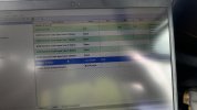
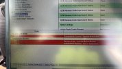
I have problam with one Cat 740 dumper ,it;s not start even dispay is not on ,i have conect the ET below cord are showing ,thos cord are active, i have ceck all power lin for ECM and TCU but i can't find problem

296-14
650-5
718-13
Please help me and pleas tell me what i have to do ,im new for cat machine
 

Nige

Senior Member
Joined
Jun 22, 2011
Messages
29,538
Location
G..G..G..Granville.........!! Fetch your cloth.
Please help me and pleas tell me what i have to do ,im new for cat machine
Well first please give a Serial Number. That will identify the appropriate electrical schematic - which you are welcome to BTW.

Your Codes....

296-14 - Transmission ECM not communicating via CAN datalink
650-5 - Harness Code. Current below normal.
718-13 - Transmission calibration required.

Can you give some information as to exactly what were the circumstances leading up to the situation in which you find yourself now.? Did the machine fail instantly or has the problem been getting worse over time until it finally stopped.?
 

Dinesh@

Member
Joined
Mar 5, 2024
Messages
11
Location
maldives
Dera

Thanks for your reply ,i was conect the ET to machine yesterday ,when we check the transmission ECM status it showing the battery voltage unavailable,the day oparator start the machine and it's run around 20 minutes and oparator stop the machine,after 1hour later he come and start the machine but it;s not start even displaye also not working ,but i have chek all power conection for display ,Engine ECM,Transmission ECM all 3 unit power is ok but CAN datalink only showing the 59 ohm, oparator told me battery charging bulb always on but it's charging

CAT00740EB1P03785
 

Nige

Senior Member
Joined
Jun 22, 2011
Messages
29,538
Location
G..G..G..Granville.........!! Fetch your cloth.
oparator told me battery charging bulb always on but it's charging
Did you measure the voltage at the batteries or at the alternator to prove that the system is charging.?

Attached some information regarding troubleshooting of the 296-14 Datalink Config Status. Not that these test DO NOT test the physical integrity of the Datalink - which TBH I suspect is likely the problem.
 

Attachments

  • 296-14.pdf
    78.3 KB · Views: 3

Dinesh@

Member
Joined
Mar 5, 2024
Messages
11
Location
maldives
Did you measure the voltage at the batteries or at the alternator to prove that the system is charging.?

Attached some information regarding troubleshooting of the 296-14 Datalink Config Status. Not that these test DO NOT test the physical integrity of the Datalink - which TBH I suspect is likely the problem.
Dera

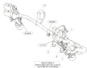
it,s very dificult to find the can resistor , schematic diagram showing the place but it,s not there,even battery is charging 27 v
 

Dinesh@

Member
Joined
Mar 5, 2024
Messages
11
Location
maldives
Did you measure the voltage at the batteries or at the alternator to prove that the system is charging.?

Attached some information regarding troubleshooting of the 296-14 Datalink Config Status. Not that these test DO NOT test the physical integrity of the Datalink - which TBH I suspect is likely the problem.
A9EAA82B-D9F4-4C7F-977D-599BF50DC584.JPGIMG_5112.jpg
 

Nige

Senior Member
Joined
Jun 22, 2011
Messages
29,538
Location
G..G..G..Granville.........!! Fetch your cloth.
Yes i have electrical schematic diagram
In that case I suggest that you start testing the CAN datalink wires using a 5A test light from battery positive to ground. A multimeter can sometimes erroneously indicate "continuity" when in actual fact the wire in question is in a bad physical state.

it,s very dificult to find the can resistor , schematic diagram showing the place but it,s not there
There is one behind the dash panel, part of harness #14. Shown on Page 6 of the schematic, Grid D-6.
The second one is shown in Grid H-5 on the same page. Physical location is in the front chassis wiring harness very close to the Engine ECM connector J-1.
i would say both of those resistors are hard-wired into their respective wiring harnesses, not plug-in.

1712461834336.png
 

Nige

Senior Member
Joined
Jun 22, 2011
Messages
29,538
Location
G..G..G..Granville.........!! Fetch your cloth.
Dera
can you tell me why it's say battery volttage unvelable,because of CAN datalink or some other problem
I think maybe the potential is there for low battery voltage (actual or implied from ECM inputs/ouputs) could cause corrupted data on the CAN network. However I am not enough of an electronics expert to say for defnite.
 

Dinesh@

Member
Joined
Mar 5, 2024
Messages
11
Location
maldives
I think maybe the potential is there for low battery voltage (actual or implied from ECM inputs/ouputs) could cause corrupted data on the CAN network. However I am not enough of an electronics expert to say for defnite.
dear

i have tack out Transmission ECM and conect saperet Transmission ECM to ET stil showing battery volttage unvelable
 

Dinesh@

Member
Joined
Mar 5, 2024
Messages
11
Location
maldives
Dera
after the schematic diagram there 5 positive cable and 5 negetive cable and 1 ignition power all conection and power is good but still showing battery volttage unvelable,please help me
 

Nige

Senior Member
Joined
Jun 22, 2011
Messages
29,538
Location
G..G..G..Granville.........!! Fetch your cloth.
the schematic diagram there 5 positive cable and 5 negetive cable and 1 ignition power. all conection and power is good
I see all of those on connector J-1 of the powertrain ECM.
Unswitched power on Pins 31, 38, 39, 46, & 47.
Switched power on Pin 1.
Ground on Pins 13, 23, 56, 57, & 70.

Did you make all the above checks with Connector J-1 connected or disconnected from the ECM.?
 

Dinesh@

Member
Joined
Mar 5, 2024
Messages
11
Location
maldives
I see all of those on connector J-1 of the powertrain ECM.
Unswitched power on Pins 31, 38, 39, 46, & 47.
Switched power on Pin 1.
Ground on Pins 13, 23, 56, 57, & 70.

Did you make all the above checks with Connector J-1 connected or disconnected from the ECM.?
Dera

Yes i have chek both way conenected and disconnected
 
Top