• Thank you for visiting HeavyEquipmentForums.com! Our objective is to provide industry professionals a place to gather to exchange questions, answers and ideas. We welcome you to register using the "Register" icon at the top of the page. We'd appreciate any help you can offer in spreading the word of our new site. The more members that join, the bigger resource for all to enjoy. Thank you!

Cat 9 pin diag port pin layout

rmllarue91

Senior Member
Joined
Apr 16, 2014
Messages
701
Location
northeast pa
Occupation
field technician
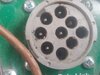
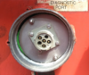
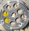
Hey hef Working on j45 McCloskey crusher Heui c9 diag port is in control panel doesn't have one near engine ecm. Plugged com 3 in no lights. Got power and ground 24vs but pin layout is totally different than trouble shooter on closer inspection the letters are different orientation. I snapped pic but quality is poor c9 s/n ThanksIMG_20210701_160228_782.jpg IMG_20210701_160228_782.jpg IMG_20210701_160228_782.jpg reh4213
 

rmllarue91

Senior Member
Joined
Apr 16, 2014
Messages
701
Location
northeast pa
Occupation
field technician
So i looked at schematic and according to s/n reh4313 the ground should be b and it's in c and as far as I know that's the normal for equipment 9 pin a power b ground. Can anyone say forsure c should be blank
 

Cmark

Senior Member
Joined
Jan 2, 2009
Messages
3,365
Location
Australia
A. is always battery +
B. Is always battery -.
Without those, your comm adapter won't work.
D and E should be CDL.
F and G should be J1939.
In theory, C gets connected to the J1939 shielding, but I don't think I've seen it used before.
 

mg2361

Senior Member
Joined
Jul 5, 2016
Messages
6,816
Location
Pennsylvania
Occupation
Equipment Mechanic
CAT must be different. I always thought the J1939 standard was this??

J1939 Standard.png
 

Birken Vogt

Charter Member
Joined
Nov 30, 2003
Messages
5,805
Location
Grass Valley, Ca
It does not even look like the pins are present in some of the places they should be. I am guessing the mfr. put their wires wherever and it is up to you to adapt them back.

If I was going to be working on this equipment a lot, I would try and make an adapter from that panel mount connector to something standard. In the meantime, I would figure out what wires are on what pins by schematic and physical/voltmeter verification if possible, and temporarily connect it with alligator clips or something.

Here is something that might work, buy this cable, shave off the center keyway, and cut/splice/rearrange wires as needed. I don't know if your existing data link connector has the fat or skinny housings on C and J, though.

https://www.ebay.com/itm/353548268546

If that Y-adapter does not have all wires where expected, I bought one of these and made my own adapter for another manufacturer's equipment:

https://www.ebay.com/itm/252959288343

If you really want to roll your own: https://www.ebay.com/itm/333979707693

My laptop bag is getting really full of cables I have made.

 

Nige

Senior Member
Joined
Jun 22, 2011
Messages
38,771
Location
G..G..G..Granville.........!! Fetch your cloth.
CAT must be different. I always thought the J1939 standard was this??
Most engines/machines I've come across use CDL (Cat DataLink) as the prime form of communication for diagnostic purposes using ET or whatever scan tool the tech happens to have. The J1939 datalink is used for a sub-program in ET called Winflash that is purely for uploading software to the ECM

Look on the back side of the plug and find some wire numbers and compare them to the snip below would be my first suggestion. 120 is power, 229 is ground. 892/893 are your twisted pair for the Datalink & 900/990 are the twisted pair for J1939.

Compared to your photo it's obvious that, in the words of the famous Chinaman, Sum Ting Wong.

upload_2021-7-4_17-5-27.png
 

Nige

Senior Member
Joined
Jun 22, 2011
Messages
38,771
Location
G..G..G..Granville.........!! Fetch your cloth.
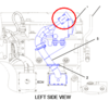
With the dagnostic port being in the control panel on this machine instead of close by the ECM on a short harness (circled) what's the betting that the OEM "re-wired" the machine to get the diagnostic connector in their preferred location and in doing so got the pinouts wrong..?

upload_2021-7-5_4-19-42.png
 

Tenwheeler

Senior Member
Joined
Dec 15, 2016
Messages
971
Location
Georgia
Is there not two different 9 pin connectors? One for off road Cats and such and the other common on trucks and such?
 

Nige

Senior Member
Joined
Jun 22, 2011
Messages
38,771
Location
G..G..G..Granville.........!! Fetch your cloth.
There is a 9-pin connector for on-highway engines that requires a different harness between the Comm Adapter and the diagnostic connector.
AFAIK for everything EXCEPT on-highway engines the pinouts on the connector are the same. This particular installation is classed as an industrial engine therefore it would come into the off-highway category.
 

Cmark

Senior Member
Joined
Jan 2, 2009
Messages
3,365
Location
Australia
Aksherly, there's two different on-highway diagnostic connectors (that I know of). Cat calls them, from memory, Paccar and ATA (American Trucking Association). I have adapters to convert them both to the off-highway connector on the Comm adapter, but I rarely use them.

I think I have these right.

ATA
upload_2021-7-5_14-8-7.png

Paccar
upload_2021-7-5_14-13-34.png
 

Birken Vogt

Charter Member
Joined
Nov 30, 2003
Messages
5,805
Location
Grass Valley, Ca
And somewhere along the line they changed the black connector to the current green one. So green test equipment will plug into black vehicles but not vise versa. The highest plastic pin tower in Cmark's picture above is smaller on the green version.
 

Birken Vogt

Charter Member
Joined
Nov 30, 2003
Messages
5,805
Location
Grass Valley, Ca
Anyway back to the Cat way of doing things, if it were mine I would probably trace out all the wires to the existing connector shell and see if they are anything like the Cat standard. Then use the pin tools available here https://obd2allinone.com/products/catconn.asp to rearrange the existing pins if you deem that appropriate.

Otherwise it could be that McCloskey had a different pinout for something proprietary of theirs but that seems doubtful to me.

I carry a connector setup with just stripped wires with me, if I find something where the connector is missing or can't figure it out, alligator clips get the job done, connect to the bus wherever it can be found, usually there are connectors here or there that have the bus present on them.
 

Jrod25

Well-Known Member
Joined
Feb 14, 2025
Messages
51
Location
Texas
Does anyone have the pin diagram for a 9 pin cdl/cat ( for a 2013 skidsteer) to that goes to the 15 pin D-sub connector? I'm starting to wonder if I'm using the wrong adapter and that is causing my issue where the J1939 isn't showing its communicating properly (incomplete).
Attached it how mine is currently wired.

I verified today I do have can signal at the port itself, it's just ET that is reporting the connection is incomplete.
 

Attachments

  • IMG_8865.jpeg
    IMG_8865.jpeg
    29.1 KB · Views: 10
  • IMG_8866.jpeg
    IMG_8866.jpeg
    89 KB · Views: 10
  • IMG_8862.jpeg
    IMG_8862.jpeg
    274.5 KB · Views: 10
  • IMG_8845.jpeg
    IMG_8845.jpeg
    402.7 KB · Views: 8

Jrod25

Well-Known Member
Joined
Feb 14, 2025
Messages
51
Location
Texas
Aftermarket. I only purchased for this one skidsteer, so not I never have connected to anything else. I was reading online, I'm not sure if it's true or not, but that cat has different 9pin to 15 d-sub pins for different applications, so idk..

I ordered another cable from one that states it's specifically for skidsteers, but it's going to be a couple weeks before it arrives. So I was hoping someone had one they could ohm out and give me the configuration pin to pin.
 

Nige

Senior Member
Joined
Jun 22, 2011
Messages
38,771
Location
G..G..G..Granville.........!! Fetch your cloth.
My money is on either the cable or the Comm Adapter, or both, being the source of the problem. From anecdotal experience aftermarket Comm Adapters & cables are fickle things.

TBH you would have been better spending your money on a used genuine OEM Comm Adapter. They come up for sale all the time on eBay.

The Datalink cable you require is Cat Part Number 457-6114. There may be a newer Part Number available.
 
Last edited:

Nige

Senior Member
Joined
Jun 22, 2011
Messages
38,771
Location
G..G..G..Granville.........!! Fetch your cloth.
I ordered another cable from one that states it's specifically for skidsteers, but it's going to be a couple weeks before it arrives. So I was hoping someone had one they could ohm out and give me the configuration pin to pin.
Not sure how they come up with that. The same cable is used for everything apart from on-highway engines for which there are a couple of different cable options if my memory serves me correctly.
 
Top