• Thank you for visiting HeavyEquipmentForums.com! Our objective is to provide industry professionals a place to gather to exchange questions, answers and ideas. We welcome you to register using the "Register" icon at the top of the page. We'd appreciate any help you can offer in spreading the word of our new site. The more members that join, the bigger resource for all to enjoy. Thank you!

D4H LGP Shift Linkage Adjustment Question

TCat

Well-Known Member
Joined
Aug 28, 2014
Messages
161
Location
Banks, Alabama USA
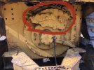
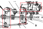
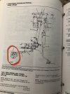
When shifting my dozer into forward, it is very difficult to get it to shift into forward gears. It was this way when I bought it and I'd like to get it working better. It will go in if I play with it and will go into all three gears, but it is very fiddly to get it into the forward three gears. Going into reverse is no problem. I want to adjust the shift linkage and looked up the procedure in the Cat service manual. The problem is I'm not sure where the actual transmission end of the linkage is. I see where the linkage goes into the top of the trans under the floorboard, but I don't see anywhere in the manual where the linkage actually ends. I suspect it's at a valve body on top of the rear of the trans and that I have to take the circled cover off to access it. I just want to make sure before I mess something up not knowing what I'm taking apart. Also If I do need to take that cover off for the adjustment, 54F31E7D-9D2E-46E0-8297-3B4038FD189D_1_201_a.jpegD245E2B3-3284-4487-9726-8DF78E79D9EB_1_201_a.jpegif I am correct there are some pressure test ports on that cover. Do those ports just have o-rings that connect them to lines or the valve body directly when you take that cover off?
Serial number for the machine is in my signature line.

Thanks in advance everyone.
 

heymccall

Senior Member
Joined
Feb 19, 2007
Messages
5,393
Location
Western Pennsylvania
Nothing in linkage is ever done thru the rear cover.
Attached is theory of powertrain.
As for difficulty in shifting, disconnect pin(s) at transmission and verify smooth action of linkages.
 

Attachments

  • D4H Ser II PT SysOp.pdf
    2.9 MB · Views: 3

Nige

Senior Member
Joined
Jun 22, 2011
Messages
29,549
Location
G..G..G..Granville.........!! Fetch your cloth.
As for difficulty in shifting, disconnect pin(s) at transmission and verify smooth action of linkages.
100%. If the linkage doesn't move smoothly with the transmission end disconnected then you have an issue in the ball joints and/or cross-shaft needle bearings - there are literally dozens of them.

If you get into cleaning/lubrication you might be well served in removing the seat to get better access to the linkage from top to bottom and disassemble it a piece at a time then refit. At some point you will more than likely find a cross shaft or spherical joint that is almost solid. Replace them, along with any joints that have obvious wear in them.

Do you have a Parts Manual that shows the linkage.? If you don't then post a Serial Number and I'll upload the parts breakdown for it.
 
Last edited:

TCat

Well-Known Member
Joined
Aug 28, 2014
Messages
161
Location
Banks, Alabama USA
Thanks Nige and Neubert. I have the seat out and the floor plates, skid plates, side panels where the batteries are off to pressure wash all the dirt and grease out of it. I swear I think this thing was sunk in a swamp or pond at some point in its' life maybe. Although I also have the dash pulled apart and that's one place I didn't find any mud, just wasp nests. Lol.

Anyway, I did take the shift linkage apart yesterday at both the shifter and the top of the transmission. A few of the rod end links do have some wear and are loose I will order some new ones. I do have a parts manual. The worst wear was in the bushing that goes in the shifter handle itself. It's pretty sloppy so I'm going to replace that as well. Moving the forward and reverse and the N,1,2,3 actuators on top of the transmission by hand without any linkage attached to it seems to feel fine from what I can tell. I would like to have actually tested the transmission by actuating the shifting by hand to test it out from right on top of the transmission to see how it would work without any linkage at all attached to it. However one of the other things I need to fix on this old girl is a broken decelerator/idle control system. I didn't want to try manually shifting the trans with no seat, no floor plate, and a faulty engine speed control system. Too many unsafe things at one time can spell disaster too quickly.
 

Nige

Senior Member
Joined
Jun 22, 2011
Messages
29,549
Location
G..G..G..Granville.........!! Fetch your cloth.
The illustration below shows just a few examples of the locations of the needle roller bearings. The bad part of those bearings is that they have no inner race and run direct on the shafts. Because they only move a few degrees they tend to hammer grooves into the shafts which makes things stick and feel "notchy". In your place I'd pull each of those shafts apart and take a good look at them.

1689951006482.png
 

TCat

Well-Known Member
Joined
Aug 28, 2014
Messages
161
Location
Banks, Alabama USA
The illustration below shows just a few examples of the locations of the needle roller bearings. The bad part of those bearings is that they have no inner race and run direct on the shafts. Because they only move a few degrees they tend to hammer grooves into the shafts which makes things stick and feel "notchy". In your place I'd pull each of those shafts apart and take a good look at them.

View attachment 290479
Wow even with all the panels I have pulled off the machine those are in a really bad place to get to. I'll have to take a look and see what else I can take off to get better access to them. At this point I don't think I can even reach them. I know I saw the two on the right through the right side of the machine deep inside. Yikes!!!
 

Nige

Senior Member
Joined
Jun 22, 2011
Messages
29,549
Location
G..G..G..Granville.........!! Fetch your cloth.
As per all the instructions for home maintenance. “Some disassembly may be required”. You might have to go as far as taking tanks off it.

I had a case on a D9R earlier this week when to remove a steel pipe in the hydraulic system we had to lift the hydraulic tank and then remove half a dozen hoses and a hydraulic block for the ripper simply to get at it. Welcome to the world of Yellow Iron.
 

TCat

Well-Known Member
Joined
Aug 28, 2014
Messages
161
Location
Banks, Alabama USA
As per all the instructions for home maintenance. “Some disassembly may be required”. You might have to go as far as taking tanks off it.

I had a case on a D9R earlier this week when to remove a steel pipe in the hydraulic system we had to lift the hydraulic tank and then remove half a dozen hoses and a hydraulic block for the ripper simply to get at it. Welcome to the world of Yellow Iron.
Yeah I get it. Bought this dozer to use for building my shop and a few other things. Need a shop for fixing the dozer first I guess. Ugh. That's alright it's good to be humbled and have to rough it sometimes.

Question for you on the Decelerator/Idle control assembly. I don't see anything in my Cat factory shop manual about the overhaul of that. I see procedures for adjusting it, but not overhauling it. I also see the parts breakdown in the parts manual. Do you have anything on that? The problem with it was that the decelerator pedal would not return to the up position. When I bought the machine they had a bungee strap hooked to it pulling it upward although not to the full up position keeping the engine from reaching full RPM unless I reached down and pulled the Decelerator up by hand.

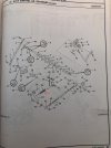
I pulled the pedal assembly off of the machine yesterday, but I have not started taking it apart yet. I thought that there would be a broken spring and that would be the problem. The spring at the bottom of the shaft is there. I suspect that the problem is in the balls, springs, and discs #4,5,33,31. Does it seem like I'm on the right track? The decelerator moves pretty easily up and down and the idle control handle seemed to move pretty well too. I'm also thinking I will replace spring #29 as well since I'm not sure it's the factory one or hasn't been altered. The end of it just doesn't look right to me. 1C171519-DCBA-4609-A941-B81761045D1E_1_201_a.jpeg
 

Nige

Senior Member
Joined
Jun 22, 2011
Messages
29,549
Location
G..G..G..Granville.........!! Fetch your cloth.
Decelerator/Idle control assembly. I don't see anything in my Cat factory shop manual about the overhaul of that. I see procedures for adjusting it, but not overhauling it. I also see the parts breakdown in the parts manual. Do you have anything on that? The problem with it was that the decelerator pedal would not return to the up position. When I bought the machine they had a bungee strap hooked to it pulling it upward although not to the full up position keeping the engine from reaching full RPM unless I reached down and pulled the Decelerator up by hand.
@tctractors would be the man to answer that. I'm more familiar with electronically-controlled governors.
 

Mark250

Senior Member
Joined
Aug 30, 2015
Messages
1,243
Location
victoria,Australia
Occupation
heavy equipment technician
my memory is not what it should be, but if i recall correctly either rod 1 or rod 45 is actually spring loaded internally
 

Mquinista

Senior Member
Joined
Jul 25, 2022
Messages
269
Location
Europe
I don´t know if it helps...
The Throtle is handle controled... not by foot. Nevertheless some dozers use a Decelerator pedal to cut engine THR.
Usually the spring is actuated by the handle, and the friction disks are used to set Handle position. Only with the handle position down full or half way, the decelerator pedal comes up and alow it to be pressed to return to idle.
 

TCat

Well-Known Member
Joined
Aug 28, 2014
Messages
161
Location
Banks, Alabama USA
I don´t know if it helps...
The Throtle is handle controled... not by foot. Nevertheless some dozers use a Decelerator pedal to cut engine THR.
Usually the spring is actuated by the handle, and the friction disks are used to set Handle position. Only with the handle position down full or half way, the decelerator pedal comes up and alow it to be pressed to return to idle.
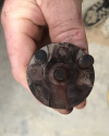
Yes that is how mine is. The handle controls the throttle with a decelerator pedal to slow the engine below the setting of the handle. The problem is that if the decelerator pedal does not return to the up position, it overrides the hand throttle and slows the engine. I have the entire assembly off the machine and torn apart now. It appears that corrosion had bound up the internals. I have some new parts on order and am working my way through it now. Will post when I get it back together. I pre-ordered a bunch of the internal parts (gaskets, rollers, seals, and springs) for it, since they were not too expensive and many were available after-market from my favorite aftermarket supplier. Truth be told I could probably just got away with cleaning it up and replacing the two seals and the two needle bearing sets on the shafts. The needle bearings weren't even locked up, but they definitely needed replaced. Pulling the assembly off and putting it back on isn't easy just because of the contorting under the dash, so I only want to have to do it once if I can help it. tempImagep2cNU6.pngtempImagegATJ7s.png
 
Top