I'm looking for a diagram of a front engine scraper powertrain. Tried search and google search and couldn't find one. Anyone have one handy they could post?? Primarily interested in the segment between the engine and the axle.

-
Thank you for visiting HeavyEquipmentForums.com! Our objective is to provide industry professionals a place to gather to exchange questions, answers and ideas. We welcome you to register using the "Register" icon at the top of the page. We'd appreciate any help you can offer in spreading the word of our new site. The more members that join, the bigger resource for all to enjoy. Thank you!
You are using an out of date browser. It may not display this or other websites correctly.
You should upgrade or use an alternative browser.
You should upgrade or use an alternative browser.
Scraper powertrain diagram
- Thread starter amtronic
- Start date
AmerIndependent
Site Sponsor
- Joined
- Nov 4, 2009
- Messages
- 359
- Location
- Riverside, CA
- Occupation
- Caterpillar Powertrain Rebuild & Repair Specialist
What model scraper?
No particular model. I'm just trying to understand how the power is transferred to the wheels from the engine. Is the transmission part of the differential assembly? Is there a driveshaft present, or a 90deg angle transfer gear arrangement?
I'm sure there are several different designs, I want to get a handle on what is out there. Maybe a 613, 641, or 660?
I'm sure there are several different designs, I want to get a handle on what is out there. Maybe a 613, 641, or 660?
AmerIndependent
Site Sponsor
- Joined
- Nov 4, 2009
- Messages
- 359
- Location
- Riverside, CA
- Occupation
- Caterpillar Powertrain Rebuild & Repair Specialist
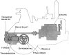
Here is an illustration of 621/623/627(frt)/631/633/637(frt)/651/657(frt)/660/666(frt)
This is an unusual arrangement where the engine drives directly from the flywheel into the back of the transmission through a set of gears and into a torque converter which is built into the planetary transmission. The output shaft of the transmission splines directly into the differential which is installed into the main frame through which a couple of splined shafts deliver power to the final drives.
The smaller 613/615 scrapers have the more traditional power train in which there is a torque converter on the back of the engine followed by drive shafts into and out of the transmission with a standard axle type.
Attachments
AmerIndependent
Site Sponsor
- Joined
- Nov 4, 2009
- Messages
- 359
- Location
- Riverside, CA
- Occupation
- Caterpillar Powertrain Rebuild & Repair Specialist
:thumbsup