HATCHEQUIP
Senior Member
Problem #1
Company that we have dealt with for years had me come look at a crane that they said the frame was flexing on. They set up that 555 "call this #1" and another that had came in from a finished job "call this #2. So 2 RT555-1 setup and leveled with levels, 4'x4' pads under out riggers both are rigged and equipped the same. Checked #1 for cracks or bends or just anything that could or might be different than #2. Stamped weight on counter weight for #1 is 200 lbs heavier, only difference we could find. Little history here #1 has just been purchased and they were dong a crane inspection certification on it, #s 2, 3 and 4 they have had for several years. Started doing picks and then maxing the chart and checking the computers against each other and load charts. I was comparing frame flexing and yes there is some but its looks the same for both units. But noticed #1s bearing moving, got a dial indicator on it. boomed it all the way up zeroed dial then boomed it down came up with .075. Had operator bounce it to see if it would keep that reading and it didnt, but noticed the bearing looked like it was really jumping forward. Measured the bearing would come forward .187 though it looked more to the eye. Picked a max chart load and the indictor went down from .075 to .110, cut the load loose boomed all the way back up and it zeroed out. Checked #2 and it didnt have enough to even bother putting the indicator on it. #1s bearings got play, bearing is made by Kaydon.
Both machines will do what there charts allow but they say #1 just feels like its going to turn over.
Problem#2
They are finding broke bolts in the swing bearings 1, 2 sometimes 3 at a time. Checked #1 and yes it has 2 popped bolts that we could see or feel.
Would like to hear thoughts from others especially similar problems with Terex 555s
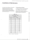
Following is Kadons charts


Following from Terex
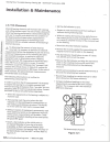
Procedure for Determining Slew Ring Wear on Terex Cranes
1. Place a dial indicator under the outer race of the bearing.
Company that we have dealt with for years had me come look at a crane that they said the frame was flexing on. They set up that 555 "call this #1" and another that had came in from a finished job "call this #2. So 2 RT555-1 setup and leveled with levels, 4'x4' pads under out riggers both are rigged and equipped the same. Checked #1 for cracks or bends or just anything that could or might be different than #2. Stamped weight on counter weight for #1 is 200 lbs heavier, only difference we could find. Little history here #1 has just been purchased and they were dong a crane inspection certification on it, #s 2, 3 and 4 they have had for several years. Started doing picks and then maxing the chart and checking the computers against each other and load charts. I was comparing frame flexing and yes there is some but its looks the same for both units. But noticed #1s bearing moving, got a dial indicator on it. boomed it all the way up zeroed dial then boomed it down came up with .075. Had operator bounce it to see if it would keep that reading and it didnt, but noticed the bearing looked like it was really jumping forward. Measured the bearing would come forward .187 though it looked more to the eye. Picked a max chart load and the indictor went down from .075 to .110, cut the load loose boomed all the way back up and it zeroed out. Checked #2 and it didnt have enough to even bother putting the indicator on it. #1s bearings got play, bearing is made by Kaydon.
Both machines will do what there charts allow but they say #1 just feels like its going to turn over.
Problem#2
They are finding broke bolts in the swing bearings 1, 2 sometimes 3 at a time. Checked #1 and yes it has 2 popped bolts that we could see or feel.
Would like to hear thoughts from others especially similar problems with Terex 555s
Following is Kadons charts


Following from Terex
Procedure for Determining Slew Ring Wear on Terex Cranes
1. Place a dial indicator under the outer race of the bearing.
- Apply a minimum downward thrust to the outer race and note the reading on the dial indicator, downward thrust can be applied by extending or lowering the boom to shift the weight to the front of the upper.
- Apply a minimum upward thrust to the outer race and note the reading on the dial indicator, upward thrust can be applied by retracting or raising the boom to shift weight to the rear of the upper.
- The difference between the readings obtained in steps 2 and 3 is the approximate internal clearance in the bearing. Compare the valve obtained with the values given for the bearing part number you are measuring.
- When the measured value exceeds the value shown the slewing ring should be replaced.
