• Thank you for visiting HeavyEquipmentForums.com! Our objective is to provide industry professionals a place to gather to exchange questions, answers and ideas. We welcome you to register using the "Register" icon at the top of the page. We'd appreciate any help you can offer in spreading the word of our new site. The more members that join, the bigger resource for all to enjoy. Thank you!

D6n parking brake won't release

Nige

Senior Member
Joined
Jun 22, 2011
Messages
29,390
Location
G..G..G..Granville.........!! Fetch your cloth.
Started machine and cycled parking brake off and on.
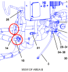
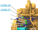
Maybe starting the engine makes it difficult to see exactly where the oil is coming from. Try disabling the injection system. On the RH side of the engine below and behind the turbo you should find a 3-pin electrical connector on a branch of the machine harness with another identical connector hanging from a loop. It's marked CONN 37 in the illustration below. If you remove the one connector and install the other one that permits you to crank the engine on the starter without it actually firing up. That way you might be able to look into the hole while cranking and be able to see where the oil is coming from.

1681827788156.png
1681827596494.png
 

Pushing forward

Well-Known Member
Joined
Mar 13, 2023
Messages
48
Location
Missouri
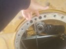
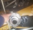
Finally had a chance to go back to machine. Here is a photo of where the oil is coming from by my fingers. Steady stream when idling and pumps more when at full throttle.
 

Attachments

  • 20230424_151152.jpg
    20230424_151152.jpg
    2.2 MB · Views: 22

tctractors

Senior Member
Joined
Oct 9, 2007
Messages
2,412
Location
Worc U.K.
That is the lube feed and little to cause you any bother, the main pressure seemed low as i recall seeing 340 psi recorded, I would have thought the top pressure would have been over 400 + psi (not to tuned in on 6N's) the Brake pressure is always higher than the Transmission as the brakes have to work first, I have had lots of brake issues and often found it to be the priority valve the culprit, by pulling the shafts and looking inwards the amount of lube oil spraying about is crazy, so I never bother with this, even looking through the back plate there always looks to be a massive spray of oil coming from the right F/Drive area, the 2 top coils on the brake valve use PWM to control them, the lower coil/s use 24 volt for the foot brake and park brake.
 

Nige

Senior Member
Joined
Jun 22, 2011
Messages
29,390
Location
G..G..G..Granville.........!! Fetch your cloth.
It is unfortunate that when you saw the oil flowing inside the rear end that you went ahead and pulled the final drive before confirming that it was necessary. The fact that oil was flowing with both the parking brake applied and with it released indicated that it was not the problem. I can understand your frustration in getting to the bottom of what's wrong but going off half-cocked isn't going to fix anything other than relieve you of large quantities of $$.
We have ruled out electrical by replacing all electrical components brake related. Could it be a foot brake issue?
If you want to get to the bottom of this then logical diagnosis is the only reliable way to move forward. It could be an issue with the service brake control but that would come out by going through the tests in a step by step fashion.
As TCT pointed out above the brake hydraulic system oil supply is prioritized over the transmission by the priority valve.
I took the valves apart and cleaned them thoroughly, making sure the screens were not plugged with debris
You posted this earlier. Can you post photos of the valves that you disasembled.

I know you said the Cat guy did the pressure tests on the brake circuit but did he test any pressures in the torque converter/transmission side.? Do you have access to a pressure gauge (1 x 35psi max & 1 x 500psi max) and the necessary hoses, fittings, etc, to do the tests.?
 

Nige

Senior Member
Joined
Jun 22, 2011
Messages
29,390
Location
G..G..G..Granville.........!! Fetch your cloth.
We have ruled out electrical by replacing all electrical components brake related.
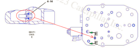
In the illustration below there are three solenoid valves. Two on top and one down below. Did you replace all three of them.?

Also you said earlier that you had opened up valves and cleaned them internally. Did you go into this one.?

1682780856919.png
 

Pushing forward

Well-Known Member
Joined
Mar 13, 2023
Messages
48
Location
Missouri
Yes did replace all three. Also cleaned all three while it was apart. Yes, I do have gauges, not sure which ports to connect to. Wasn't able to make it out to the machine to get pictures.
 

Nige

Senior Member
Joined
Jun 22, 2011
Messages
29,390
Location
G..G..G..Granville.........!! Fetch your cloth.
Yes did replace all three.
When you removed the three solenoids to replace them did you also remove the complete valve from the machine and disassemble the guts inside each of the different sections of the valve body in the illustration above.?
Parts are broken down as per attachment.
 

Attachments

  • Brake Valve.pdf
    605.5 KB · Views: 14

Pushing forward

Well-Known Member
Joined
Mar 13, 2023
Messages
48
Location
Missouri
Yes, pulled everything apart, saw nothing. Sprayed with brake cleaner just in case there was something I didn't see and reassembled
 

Nige

Senior Member
Joined
Jun 22, 2011
Messages
29,390
Location
G..G..G..Granville.........!! Fetch your cloth.
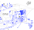
Things in the electronic system to check. There are two resistors marked 14 & 15 on the illustration below. They are located just below the circuit breaker panel marked "B". Disconnect each one in turn, check the Part Numbers just to be on the safe side, and measure the resistance.
Do NOT get them mixed up, they are different Part Numbers but the connectors for them on the machine harness are identical.

1682952034599.png
1682952247234.png
 

Nige

Senior Member
Joined
Jun 22, 2011
Messages
29,390
Location
G..G..G..Granville.........!! Fetch your cloth.
I checked the resistors, one read 1.508 and the other read .503.
Was that measuring in KΩ.? If so that is correct because one is rated at 500Ω and the other at 1500Ω.
What range is acceptable for the duty cycle?
When the service brake pedal is up the sensor should measure close to zero %, certainly less than 5% I would have thought. With the pedal pressed all the way down it should be 95+% duty cycle.
 

Nige

Senior Member
Joined
Jun 22, 2011
Messages
29,390
Location
G..G..G..Granville.........!! Fetch your cloth.
Obviously you will need the key on. I'm not 100% sure whether you will need the engine running or not. try it with the engine stopped first.

While you are in that area you could also check the operation of the pedal position switch. The wires in the machine harness connected to it are 198 Red and G731 Grey. That switch contacts should remain open until you press the pedal right to the bottom of its travel. At that point the contacts should close. Closing the contacts of that switch applies the parking brake.

1683335036856.png

See the illustration of the brake control valve in Post #47 above. After you've tested the pedal position sensor signal and the operation of the pedal position switch go to the brake valve and measure the current being supplied to the proportional solenoid valve (#12). You'll have to do this with all the wiring hooked up and the engine running. As the service brake pedal is pressed the current to the PSV should reduce.
 

Nige

Senior Member
Joined
Jun 22, 2011
Messages
29,390
Location
G..G..G..Granville.........!! Fetch your cloth.
When you first posted you went straight into the story about how the parking brake wouldn't release and what the Cat mechanic had done and/or recommended.

Can you give a bit more back story (if there is any) on anything that you think might be relevant that happened in the time leading up to the point where the park brake quit releasing. Was it an overnight issue; good one day, not working the next; or did the problem slowly build up to the point where the brake wouldn't release.?
 
Top