• Thank you for visiting HeavyEquipmentForums.com! Our objective is to provide industry professionals a place to gather to exchange questions, answers and ideas. We welcome you to register using the "Register" icon at the top of the page. We'd appreciate any help you can offer in spreading the word of our new site. The more members that join, the bigger resource for all to enjoy. Thank you!

Hitachi zx75 ur. Thumb/swing boom issues

Chantrelle

Member
Joined
Nov 23, 2023
Messages
8
Location
Lasqueti island
this is my first post in here. Please let me know if the post is not clear and concise enough….

Ive owned a hitachi zx75 ur for about 5 years now. My first machine. I live on an isolated island without a machine mechanic so am having to figure out how to do maintenance and repairs best I can.

The thumb on the machine was put on by the guy I bought it from. So after market. For the last hundred hours or so the thumb opens at normal speed but closes super slow and won’t stay fully closed when gravity is pulling it down or if it’s got a log or rock between bucket and thumb. So when I lift a log up if I don’t keep my foot on the thumb pedal it will start to open and fumble or drop the log.

The thumb hydraulic lines comes from an oil directional control unit mounted on the side of the boom which I can control in he cab and activate the thumb or the swing boom.

The swing boom is controlled by a ram which has begun to have some movement/ play when I turn the machine from side to side. This movement/play in the swing boom gets pretty bad. If I switch the oil between thumb and swing boom the movement goes away for a bit.

So the movement int the swing boom and the slow thumb may have the same source.

When I follow the hydraulic line from the direction control unit i end up near the valve bank at a small metal box.I’m not sure what the box is but I think it’s may be some kind of pressure relief valve. A Hydraulic line comes in one end of the box and out the other. Then splits at a T and goes to both the hydraulic tank and what looks like unit the valve bank.

I have had the thumb cylinder seals replace and the unit inspected. I’ve also had the directional control unit inspected. It has been sugggested that there may be an issue with a pressure relief valve needing to be adjusted.

So all that being said. It seems possible the little box that may be a pressure relief valve may need to be adjusted or replaced. I’ve never dealt with anything to do with the valves or pressure in the machine so have no idea what pressure I’m looking for or if it that would even be my problem. I have purchased an online manual but find it far from helpful.

This feels like a very long winded post but I figure the more information the better likely good that someone may be able to make sense of what going on.

Any advice is appreciated

Thanks.


here’s a picture of the direction control unit. I don’t have a pic of what I think is a relief valve. E28EEE09-0C95-419A-A525-0D98009E5AC8.jpeg
 

uffex

Senior Member
Joined
Jan 23, 2012
Messages
4,464
Location
Lincoln UK
Occupation
Admin
Good day & welcome
I will try to help but you need to get busy with a camera, most thumb installations are made by third party's. This can make it difficult to establish what you are working with and even more difficult for remote diagnostics. Start at the thumb cylinder photo the lines at any connection - valve labels ect.
I will try to make a schematic and some diagnostic recommendations.
Kind regards
Uffex
 

Chantrelle

Member
Joined
Nov 23, 2023
Messages
8
Location
Lasqueti island
Ok. Pictures. Here we go.
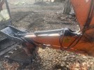
Thumb

1st pic. Thumb cylinder

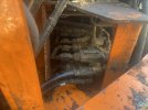
2nd pic. Direction control unit.

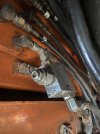
3rd pic. Possible pressure release valve but I’m not sure. The black house that comes out of the right side of direction control unit(see 2nd pic)goes into this box which is located right next to main valve bank.

4th pic. The line from the unit in the 3rd pic goes to a t which sends a line into the hydraulic tank. The other line goes down to the unit in the fourth pic. I’ll include a few more pics I. The next post. 4 is the limit.

5D6FBC93-6D04-4E99-AA6F-398D3A3B220F.jpeg

B258EA6B-5EAE-4E38-A8E4-8804AB1C8AA9.jpeg0F28FA3A-8F92-488E-ACB6-EBBE0E4A577D.jpeg3CAA8DAD-08EF-4DCB-89D3-F2026224A15C.jpeg
 

Chantrelle

Member
Joined
Nov 23, 2023
Messages
8
Location
Lasqueti island
5th pic. Shot from further out of pic 4.

6th pic. Swing boom


Let me know what other pics I should get you.

I did notice some of the hoses have some damage. The rubber is cracking and missing in spots. Can old hoses cause issues in the ability of the oil to flow?

Thanks so much for the help.
image.jpg6E21226F-F908-4BFE-A1AF-56B464ABA9B1.jpeg
 

uffex

Senior Member
Joined
Jan 23, 2012
Messages
4,464
Location
Lincoln UK
Occupation
Admin
Good day
I will make something of your information, just to be sure, we have loss of flow (Speed) could be leakage and could be a combination of faults. Check the pedal has no obstructions, I will come back to you in due course.
Kind regards
Uffex
 

uffex

Senior Member
Joined
Jan 23, 2012
Messages
4,464
Location
Lincoln UK
Occupation
Admin
Good day
Im not too sure as to the relief valve connection see attached.
As the negative effect is to both the thumb and boom swing and I guess you have limited resources being isolated, I suggest a staring point maybe to disconnect the extra parts added by the addition of the thumb and test to see if boom swing is OK.
Kind regards
Uffex
 

Attachments

  • ZX75 Thumb.pdf
    7 MB · Views: 11

Chantrelle

Member
Joined
Nov 23, 2023
Messages
8
Location
Lasqueti island
I’m not certain that the little metal box is a relief valve. It’s just a theory. Does it look to you like a relief valve?

As to on the connection tkk ok that “relief valve”. There is line coming from the directional control unit. It come out the right side of you look at picture. (Has black tape on it). And that head back towards valve bank and goes into the relief valve. On the other side on the relief valve a line exits and hits a T. At the T one line goes directly into oil tank. The other goes down to the unit in picture 4/5.

If you look at the picture of the control unit there is also two orange steel lines(pic 1)that connect on the right side of the box. They head back into what I believe is the main valve bank (pic 2). I’ll try to include pictures of where they go.

Theirs is nothing obstructing the pedal.

I have a buddy with a kit for checking oil pressure. I just don’t know
A)what pressure I’m after.
B) how to adjust pressure
C) if the issues I’m having would be at all related to a pressure issue.

Thanks again.


00C3D73D-6406-4834-A8CA-392BD1855A38.jpeg1E3C0252-D792-4B15-91F7-763ABBA9F5D5.jpeg
 

uffex

Senior Member
Joined
Jan 23, 2012
Messages
4,464
Location
Lincoln UK
Occupation
Admin
Good day
The third photo of your second post appears like a relief valve, I have researched the number on the valve housing, the nearest I can find is a valve by Sun Hydraulics. It is good practice to install a relief valve to the positive side of the thumb cylinder. I am taking a guess this is what it is.
Missing is any refill valve, if you relive the thumb on one side you must let fluid enter the opposite end. I do not have a schematic for the boom swing it has a component with three connections as I see it. Negative - positive and tank.I interpret your post as fluid loss reducing flow to the cylinders. Short of isolating the thumb parts I would suspect the relief valve, this offers another test solution. Plug the relief valve tank line I believe this is the line you are pointing out. Be avoid fully stroke the cylinders but test the boom swing if it recovers and operates normally we can pin point the relief valve. As the circuit has no refill valve that I can see I would remove the valve dismantle it on the bench I attach a explanation of what to look for.
Kind regards
Uffex
 

Attachments

  • Relief trouble.pdf
    701.4 KB · Views: 3

Chantrelle

Member
Joined
Nov 23, 2023
Messages
8
Location
Lasqueti island
Hey uffex thanks for the reply.

I’d like to clear a few things up.

1). When you refer to positive side of the cylinder. Would that be the line coming from the rod end port of the cylinder. That I assume would carry fluid back to the tank when the rod is being pushed out?

2). The line that I’m pointing to at the relief valve is the line that is coming directly from the direction control unit.

It sound like you are suggesting plugging the line that goes directly into the oil reservoir. Which would be after the T on the back side of the box in that picture. Does that sounds correct?

Or are you suggesting to plug the line before it get to the release valve? Are there any problems that can be caused by moving the cylinders with this line plugged?

3) you instruct me to “Be avoid fully stroke the cylinders but test the boom swing if it recovers and operates normally we can pin point the relief valve. As the circuit has no refill valve that I can see I would remove the valve dismantle it on the bench I attach an explanation of what to look for.”

I’m having trouble making sense of this instruction.


What do you mean by “be avoid fully stroke the cylinders?

What is a refill valve?

4). The swing boom issues are pretty well not existent when the machine is not warmed up. It’s only after it’s warmed that there starts to be some play in the ram. Also I tested to see if there was a difference in speed side to side in the swing boom and it seems like the speed is the same moving left or right. So the only issue is the build up of movement in the ram. But I can’t really test it without using it for a while.

Okay thanks for your patience here.
 

uffex

Senior Member
Joined
Jan 23, 2012
Messages
4,464
Location
Lincoln UK
Occupation
Admin
Good day
No.1 I refer to the positive end means the piston end not the rod end. It is less probable that the rod side will suffer from over pressure.
No.2. The line goes back to the valve block from the relief valve I have guessed connects to a tank line at the valve block. If you can get a hydraulic schematic for your machine I can be sure. "T" always refers to Tank return line.If we assume the relief is adopting a open position blocking the tank line will prevent this affecting your boom swing.
No.3 I mean avoid fully stroking the cylinders (Boom swing) will prevent any high pressure. We are concerned with fluid flow and leakage of that flow. Sorry if my explanation is not so good, when the fellow made your thumb installation he overlooked the point if you let fluid out of one side of the cylinder you must let fluid in on the opposing side. If not when the relief valve opens you get cavitation the cylinder flaps back and forth with little control. Can also cause issues like Orins being sucked from there position.
Do not be concerned about clarification of my explanations. your questions make my explanations better quality.
Kind regards
Uffex
 

Attachments

  • Cylinder explaination.pdf
    694.5 KB · Views: 2

uffex

Senior Member
Joined
Jan 23, 2012
Messages
4,464
Location
Lincoln UK
Occupation
Admin
Good day
Additional information
Kind regards
Uffex
 

Attachments

  • ZX75 Thumb2.pdf
    767.2 KB · Views: 6

uffex

Senior Member
Joined
Jan 23, 2012
Messages
4,464
Location
Lincoln UK
Occupation
Admin
Good day
That does appear to be a relief valve, can you plug the lines - remove the valve to the bench and dismantle. Dont worry you cannot damage this by removal - dismantle.
Kind regards
Uffex
 

Chantrelle

Member
Joined
Nov 23, 2023
Messages
8
Location
Lasqueti island
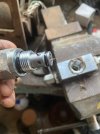
Well I found the culprit.

I did have some damage to the thumb cylinder a while back. Perhaps that where the metal shard came from.

Probably better to get stuck in release valve than valve bank. But it does make me wonder if there more debris floating around and what kind of damage it can cause.

There was no oil in the line that went to the relief valve. Which I don’t fully understand….

Messing around with these lines has shined a light on my ignorance around the hydraulic system. Thanks for helping me understand it a little better.

Cheers.

9963B591-71EE-4241-9026-8B390A5C4A3B.jpeg
 

uffex

Senior Member
Joined
Jan 23, 2012
Messages
4,464
Location
Lincoln UK
Occupation
Admin
Well I found the culprit.

I did have some damage to the thumb cylinder a while back. Perhaps that where the metal shard came from.

Probably better to get stuck in release valve than valve bank. But it does make me wonder if there more debris floating around and what kind of damage it can cause.

There was no oil in the line that went to the relief valve. Which I don’t fully understand….

Messing around with these lines has shined a light on my ignorance around the hydraulic system. Thanks for helping me understand it a little better.

Cheers.

View attachment 299605
Great would you please be so kind as to give a photo of the numbers on that valve, I believe that valve is mounted above your tank fluid line any leakage will drain the line.Keep smiling Uffex
 

uffex

Senior Member
Joined
Jan 23, 2012
Messages
4,464
Location
Lincoln UK
Occupation
Admin
Good day
I should have pointed out to change your filters, the root cause of the cylinder failure could well be absence of a refill valve, I would recommend that you take the trouble, not such a big cost at this point.
Kind regards
Uffex
 
Top